S8VS
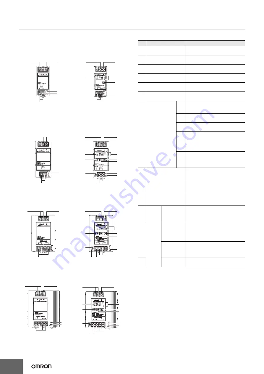
Construction and Nomenclature
(60-W, 90-W, 120-W, 180-W, 240-W, and 480-W Models)
Nomenclature
60-W Models
Standard Model
S8VS-06024
1
2
4
5
3
90-W/120-W Models
Standard Models
S8VS-09024/S8VS-0924S/
S8VS-12024
1
2
Models with Indication Monitor
S8VS-06024
@
1
2
6
7
8
4
5
3
3
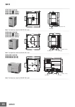
Note: The S8VS-06024A is shown above.
Models with Indication Monitor
S8VS-09024
@@@
/
S8VS-09024
@@@
S/S8VS-12024
@@@
1
2
6
7
No.
Name
1
AC Input terminals
(L), (N)
Protective Earth
2
terminal (PE)
DC Output terminals
3
(
−
V), (+V)
4
Output indicator
(DC ON: Green)
5
Output voltage
adjuster (V.ADJ)
6
Main display (Red)
*
4
Operation
7
indicator
(Orange)
*
4
8
Mode Key
*
4
9
Up Key
*
5
10 Down Key
*
5
V
A
Apk
Yrs
kh
Function
Connect the input lines to these
terminals.
*
1
Connect the ground line to this
terminal.
*
2
Connect the load lines to these
terminals.
Lights while a direct current (DC)
output is ON.
Use to adjust the voltage.
*
3
Indicates the measurement or set
value.
Lights up when the output voltage is
indicated. Blinks during setup of
undervoltage alarm value.
Lights up during indication of output
current.
Lights up during indication of peak
hold current.
Lights up during indication of
maintenance forecast monitor.
Blinks during setup of maintenance
forecast monitor setting. (S8VS
@@@
24A
@@
)
Lights up during indication of total
run time monitor. Blinks during setup
of total run time monitor. (S8VS
@@@
24B
@@
)
Use the Mode Key to change the
indicated parameter or reset the
peak hold current value.
Use the Up Key to change to the
setting mode or to increase the set
value.
Use the Down Key to change to the
setting mode or to decrease the set
value.
Output when a drop is detected in
the output voltage (voltage drop =
transistor OFF).
Output when the set value for
maintenance is reached (transistor
OFF).
Output when the set value for total
run time is reached (transistor OFF).
Common terminal (emitter) for
terminals 11 and 12.
3
180-W Models
Standard Model
S8VS-18024
1
3
240-W Models
Standard Model
S8VS-24024
1
2
10
8
9
4
12
4
5
5
1113 3
Note: The S8VS-12024A is shown above.
Models with Indication Monitor
S8VS-18024
@@@
2
1
2
6
7
10
8
9
4
12
4
5
5
11 13 3
Note: The S8VS-18024A is shown above.
Models with Indication Monitor
S8VS-24024
@@@
1
2
6
7
10
8
9
4
12
4
5
5
3
11 13 3
Note: The S8VS-24024A is shown above.
*
The terminal arrangement is the same for models with screwless
terminal blocks and standard models.
Undervoltage
11
output
terminal (DC
Low)
Maintenance
Forecast
Alarm
output
outputs terminal (Yrs)
12
*
5,
*
6
*
7
Total run time
output
terminal (kh)
*
8
Common
13
terminal
*1.
The fuse is located on the (L) side. For a DC input, connect the
positive voltage to the L terminal.
*2.
This is the protective earth terminal specified in the safety
standards. Always ground this terminal.
*3.
The output voltage cannot be adjusted for the
S8VS-09024
*4.
S8VS-
@@@
24A
@@
/B
@@
/BE
@
only.
*5.
S8VS-
@@@
24A
@@
/B
@@
*6.
Both sinking and sourcing outputs are available.
*7.
S8VS-
@@@
24A
@@
only (excluding S8VS-06024A).
*8.
S8VS-
@@@
24B
@@
only (excluding S8VS-06024B).
16
Summary of Contents for S8VS 120-W
Page 34: ...MEMO 34 ...


