


XW5T
21
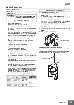
Installation
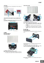
You can bend and cut off any of the middle pins with a tool when you
use a Short Bar.
If a Short Bar that has the required pins is not available, you can
combine more than one Short Bar to short the required Terminal
Blocks.
For example, the following figure shows combining Four-pin and Five-
pin Short Bars to short eight Terminal Blocks.
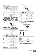
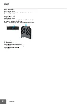
Labels
Mounting Method
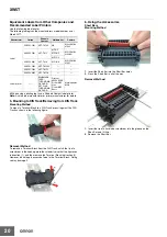
Top-surface Labels
1.
Remove the Labels one at a time.
2.
Insert them on the tops of the Terminal Blocks.
Note:
If multiple Terminal Blocks of the same type are used side by
side, you can use multiple Labels still connected to each other.
Side-surface Labels
1.
Remove the Labels one at a time.
2.
Insert them on the sides of the Terminal Blocks.
Note: 1.
There is no place to mount the Top-surface Labels on Two-
tier Terminal Blocks with a width of 3.5 mm, so they cannot
be used.
2.
Different models of Labels are used for the top and side
surfaces.
3.
If multiple Terminal Blocks of the same type are used side
by side, you can use multiple Labels still connected to each
other.
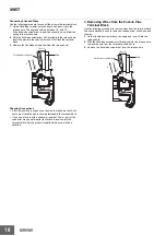
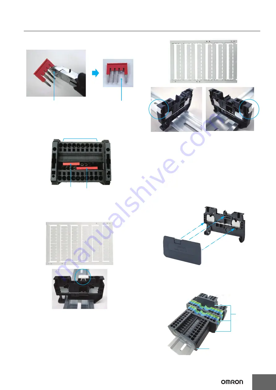
End Cover
Mounting Method
Attach the End Cover to the side of the Terminal Block with exposed
metal.
Always mount End Covers to the following locations when you use
Terminal Blocks.
(1) Exposed metal surface of the last Terminal Block
(2) Any Terminal Block that is next to a different shape of Terminal Block
There is a risk of electric shock if End Covers are not used.
Note:
End Brackets or Separator Plate cannot be used in place of an
End Cover.
Bend.
Cut.
S
horting 8 Termin
a
l Block
s
.
Fo
u
r-pin
S
hort B
a
r
Five-pin
S
hort B
a
r
Terminal Block
End Cover
(1)
(2)


