background image

XW5T

6

Feed Through Terminal blocks Multi tiers terminal

*1.

For the recommended applicable wire ranges, refer to page 17 for solid and stranded wires, and to page 19 for ferrules.

*2.

You can also use ferrules for 1.0 to 1.5 mm

2

 wires if you use ferrules without insulation sleeve. Refer to page 19 for details.

*3.

Do not apply more than the rated current to the terminal block.

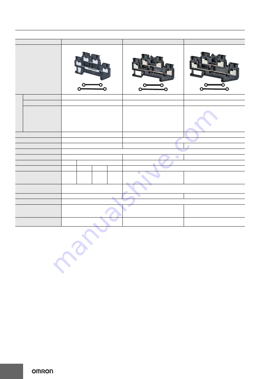
Model

XW5T-P1.5-1.1-2 (BL)

XW5T-P2.5-1.1-2 (BL)

XW5T-P4.0-1.1-2 (BL)

Appearance and internal 
wiring

2 tiers, 1:1

2 tiers, 1:1

2 tiers, 1:1

A

p

p

li

c

ab

le

 w

ire

 si

ze

s*

1

Stranded wire

0.08 mm

2

 to 1.5 mm

2

0.14 mm

2

 to 2.5 mm

2

0.2 mm

2

 to 4.0 mm

2

Solid wire

0.14 mm

2

 to 1.5 mm

2

0.14 mm

2

 to 4.0 mm

2

0.2 mm

2

 to 6.0 mm

2

Stranded wire with 
ferrule with Plastic 
sleeve

0.14 mm

2

 to 0.75 mm

2

 (1.5 mm

2

) *2

0.14 mm

2

 to 2.5 mm

2

0.25 mm

2

 to 4.0 mm

2

Dimensions

3.5 × 65.7 × 41.1

5.2 × 78.8 × 45.9

6.2 × 85 × 45.9

Rated voltage

500 V

600 V

Rated current *3

17.5 A

22 A

28 A

IEC rated voltage

500 V

IEC rated current *3

17.5 A/1.5 mm

2

22 A/2.5 mm

2

28 A/4.0 mm

2

Usage Group (UG)

B, C

D

B, C

UL rated voltage

300 V

51-150 V

151-300 V

301-600 V

600 V

UL rated current *3

15 A/AWG14 
(SOL)
10 A/AWG16

15 A/AWG14 
(SOL)
10 A/AWG16

10 A/
AWG16

5 A/
AWG16-20

20 A/AWG12 (SOL), 
15 A/AWG14

30 A/AWG10 (SOL), 
20 A/AWG12

Dielectric strength

1,890 VAC for 1 min 
(leakage current: 1 mA max.)

2,000 VAC for 1 min 
(leakage current: 1 mA max.)

End Cover

XW5E-P1.5-1.1-2

XW5E-P2.5-1.1-2

XW5E-P4.0-1.1-2

Special tool

XW4Z-00B

Applicable nameplates

XW5Z-P1.5LB2

XW5Z-P2.5LB

@

 or commercially available 

nameplate with 9.5 mm width and 0.5 mm 
thickness

XW5Z-P4.0LB

@

 or commercially available 

nameplate with 9.5 mm width and 0.5 mm 
thickness

Applicable Short Bars

XW5S-P1.5-

@


(

@

: Poles = 2, 3, 4, 5 or 10)

XW5S-P2.5-

@


(

@

: Poles = 2, 3, 4, 5 or 10)

XW5S-P4.0-

@


(

@

: Poles = 2, 3, 4, 5 or 10)

Summary of Contents for XW5T

Page 1: ... less wiring work and high reliability Hands free structure that holds an inserted screwdriver to achieve better workability when wiring stranded wires without crimp terminals Model Number Legend Refer to Safety Precautions on page 17 For the most recent information on models that have been certified for safety standards refer to your OMRON website XW5T P XW5G P Feed Through Terminal Blocks Ground...

Page 2: ... DIN Track Terminal Blocks Both Feed Through and Grounding Terminal Blocks are available End Cover This part is required to prevent electric shock Attach one End Cover to the exposed metal surface of the last Terminal Block or to any Terminal Block that is next to a different shape of Terminal Block End Brackets End Brackets must be attached to both ends to hold the Terminal Block in place Namepla...

Page 3: ... 4 0 1 3 10 8 XW5T P4 0 1 2 1 0 08 to 1 5 1 3 Blue 4 1 XW5T P1 5 1 2 1BL 0 14 to 2 5 1 3 8 2 XW5T P2 5 1 2 1BL 0 2 to 4 0 1 3 10 8 XW5T P4 0 1 2 1BL 0 08 to 1 5 1 4 Dark grey 4 9 XW5T P1 5 2 2 1 0 14 to 2 5 1 4 10 4 XW5T P2 5 2 2 1 0 2 to 4 0 1 4 13 4 XW5T P4 0 2 2 1 0 08 to 1 5 1 4 Blue 4 9 XW5T P1 5 2 2 1BL 0 14 to 2 5 1 4 10 4 XW5T P2 5 2 2 1BL 0 2 to 4 0 1 4 13 4 XW5T P4 0 2 2 1BL Grounding Te...

Page 4: ...in blank XW5Z P1 5LB2 1 sheet with 108 side labels 5 XW5 P2 5 XW5Z P2 5LB1 1 sheet with 72 top labels 5 XW5Z P2 5LB2 1 sheet with 72 side labels 5 XW5 P4 0 XW5Z P4 0LB1 1 sheet with 60 top labels 5 XW5Z P4 0LB2 1 sheet with 60 side labels 5 Appearance Applicable Terminal Blocks Model Application XW5 P1 5 1 1 1 XW5E P1 5 1 1 1 This part is required to prevent electric shock Always mount End Covers ...

Page 5: ... 6 2 56 1 35 3 Rated voltage 500 V 800 V Rated current 3 17 5 A 24 A 32 A IEC rated voltage 500 V 800 V 800 V IEC rated current 3 17 5 A 1 5 mm2 24 A 2 5 mm2 32 A 4 0 mm2 Usage Group UG B C D B C UL rated voltage 300 V 51 150 V 151 300 V 301 600 V 600 V UL rated current 3 15 A AWG14 SOL 10 A AWG16 15 A AWG14 SOL 10 A AWG16 10 A AWG16 5 A AWG16 20 20 A AWG12 SOL 15 A AWG14 30 A AWG10 SOL 20 A AWG12...

Page 6: ... mm2 0 25 mm2 to 4 0 mm2 Dimensions 3 5 65 7 41 1 5 2 78 8 45 9 6 2 85 45 9 Rated voltage 500 V 600 V Rated current 3 17 5 A 22 A 28 A IEC rated voltage 500 V IEC rated current 3 17 5 A 1 5 mm2 22 A 2 5 mm2 28 A 4 0 mm2 Usage Group UG B C D B C UL rated voltage 300 V 51 150 V 151 300 V 301 600 V 600 V UL rated current 3 15 A AWG14 SOL 10 A AWG16 15 A AWG14 SOL 10 A AWG16 10 A AWG16 5 A AWG16 20 20...

Page 7: ...54 1 30 5 5 2 60 5 35 3 6 2 66 5 35 3 Rated voltage 500 V 800 V Rated current 3 17 5 A 24 A 32 A IEC rated voltage 500 V 800 V IEC rated current 3 17 5 A 1 5 mm2 24 A 2 5 mm2 32 A 4 0 mm2 Usage Group UG B C D B C UL rated voltage 300 V 51 150 V 151 300 V 301 600 V 600 V UL rated current 3 15 A AWG14 SOL 10 A AWG16 15 A AWG14 SOL 10 A AWG16 10 A AWG16 5 A AWG16 20 20 A AWG12 SOL 15 A AWG14 30 A AWG...

Page 8: ... 76 9 35 3 Rated voltage 500 V 800 V Rated current 3 17 5 A 24 A 32 A IEC rated voltage 500 V 800 V IEC rated current 3 17 5 A 1 5 mm2 24 A 2 5 mm2 32 A 4 0 mm2 Usage Group UG B C D B C UL rated voltage 300 V 51 150 V 151 300 V 301 600 V 600 V UL rated current 3 15 A AWG14 SOL 10 A AWG16 15 A AWG14 SOL 10 A AWG16 10 A AWG16 5 A AWG16 20 20 A AWG12 SOL 15 A AWG14 30 A AWG10 SOL 20 A AWG12 Dielectri...

Page 9: ...mm2 to 1 5 mm2 0 14 mm2 to 2 5 mm2 0 2 mm2 to 4 0 mm2 Solid wire 0 14 mm2 to 1 5 mm2 0 14 mm2 to 4 0 mm2 0 2 mm2 to 6 0 mm2 Stranded wire with ferrule with Plastic sleeve 0 14 mm2 to 0 75 mm2 1 5 mm2 2 0 14 mm2 to 2 5 mm2 0 25 mm2 to 4 0 mm2 Dimensions 3 5 45 30 5 5 2 48 8 35 3 6 2 56 1 35 3 IEC rated voltage 500 V 800 V UL rated voltage 600 V Dielectric strength 1 890 VAC for 1 min leakage curren...

Page 10: ...Applicable wire sizes 1 Stranded wire 0 08 mm2 to 1 5 mm2 0 14 mm2 to 2 5 mm2 0 2 mm2 to 4 0 mm2 Solid wire 0 14 mm2 to 1 5 mm2 0 14 mm2 to 4 0 mm2 0 2 mm2 to 6 0 mm2 Stranded wire with ferrule with Plastic sleeve 0 14 mm2 to 0 75 mm2 1 5 mm2 2 0 14 mm2 to 2 5 mm2 0 25 mm2 to 4 0 mm2 Dimensions 3 5 65 7 41 1 5 2 78 8 45 9 6 2 85 45 9 IEC rated voltage 500 V UL rated voltage 600 V Dielectric streng...

Page 11: ...mm2 to 1 5 mm2 0 14 mm2 to 2 5 mm2 0 2 mm2 to 4 0 mm2 Solid wire 0 14 mm2 to 1 5 mm2 0 14 mm2 to 4 0 mm2 0 2 mm2 to 6 0 mm2 Stranded wire with ferrule with Plastic sleeve 0 14 mm2 to 0 75 mm2 1 5 mm2 2 0 14 mm2 to 2 5 mm2 0 25 mm2 to 4 0 mm2 Dimensions 3 5 54 1 30 5 5 2 60 5 35 3 6 2 66 5 35 3 IEC rated voltage 500 V 800 V UL rated voltage 600 V 600 V Dielectric strength 1 890 VAC for 1 min leakag...

Page 12: ...25 mm2 to 4 0 mm2 Dimensions 3 5 63 2 30 5 5 2 72 2 35 3 6 2 76 9 35 3 IEC rated voltage 500 V 800 V UL rated voltage 600 V Dielectric strength 1 890 VAC for 1 min leakage current 1 mA max 2 000 VAC for 1 min leakage current 1 mA max End Cover XW5E P1 5 2 2 1 XW5E P2 5 2 2 1 XW5E P4 0 2 2 1 Special tool XW4Z 00B Applicable nameplates XW5Z P1 5LB or commercially available nameplate with 9 5 mm widt...

Page 13: ...1 5 1 2 1 24 5 30 5 63 2 3 5 XW5T P1 5 2 2 1 BL XW5G P1 5 2 2 1 35 1 41 1 24 5 30 5 65 4 3 5 XW5T P1 5 1 1 2 BL XW5G P1 5 1 1 2 29 4 35 3 48 8 5 2 XW5T P2 5 1 1 1 BL XW5G P2 5 1 1 1 5 2 29 4 35 3 60 5 XW5T P2 5 1 2 1 BL XW5G P2 5 1 2 1 5 2 29 4 35 3 72 2 XW5T P2 5 2 2 1 BL XW5G P2 5 2 2 1 40 45 9 78 8 5 2 29 4 35 3 XW5T P2 5 1 1 2 BL XW5G P2 5 1 1 2 ...

Page 14: ... 1 1 2 3 5 No of poles 1 2 3 1 6 3 3 5 18 2 P XW5S P1 5 Model P mm XW5S P1 5 2 3 5 XW5S P1 5 3 7 0 XW5S P1 5 4 10 5 XW5S P1 5 5 14 0 XW5S P1 5 10 31 5 XW5S P2 5 Model P mm XW5S P2 5 2 5 2 XW5S P2 5 3 10 4 XW5S P2 5 4 15 6 XW5S P2 5 5 20 8 XW5S P2 5 10 46 8 5 2 23 3 1 6 5 2 No of poles 1 3 7 P XW5S P4 0 Model P mm XW5S P4 0 2 6 2 XW5S P4 0 3 12 4 XW5S P4 0 4 18 6 XW5S P4 0 5 24 8 XW5S P4 0 10 55 8 ...

Page 15: ...45 XW5E P1 5 1 1 1 2 2 54 1 24 5 XW5E P1 5 1 2 1 2 2 63 2 24 5 XW5E P1 5 2 2 1 2 2 65 4 35 1 XW5E P1 5 1 1 2 2 2 48 8 29 4 XW5E P2 5 1 1 1 2 2 60 5 29 2 XW5E P2 5 1 2 1 2 2 72 2 29 2 XW5E P2 5 2 2 1 2 2 39 8 78 8 XW5E P2 5 1 1 2 ...

Page 16: ...rackets Separator Plates 2 2 56 1 29 4 XW5E P4 0 1 1 1 2 2 66 5 29 2 XW5E P4 0 1 2 1 2 2 76 9 29 2 XW5E P4 0 2 2 1 2 2 85 39 8 XW5E P4 0 1 1 2 55 6 40 2 33 5 XW5Z EP6 End Brackets XW5Z EP12 Separator Plates 12 63 56 ...

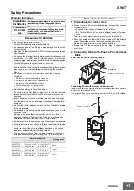
Page 17: ...m so that the conductive parts of adjacent Terminal Blocks are facing in the same direction If they face in different directions short circuits may occur between adjacent Terminal Blocks To prevent wire materials from smoking or igniting confirm wire ratings and use the wiring materials given in the following table 1 Precautions for Correct Use Always mount End Covers to the following locations wh...

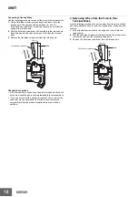
Page 18: ...l not come off and the wire is securely fastened to the terminal block If you use a ferrule with a conductor length of 10 mm part of the conductor may be visible after the ferrule is inserted into the terminal block but the product insulation distance will still be satisfied 3 Removing Wires from the Push In Plus Terminal Block Use the following procedure to remove wires from the terminal block Th...

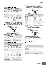
Page 19: ...16 202 10 12 AI 0 75 10 H0 75 16 216 242 Recommended crimp tool CRIMPFOX6 CRIMPFOX6T F CRIMPFOX10S PZ6 roto Variocrimp4 Applicable wire Ferrule Conductor length mm Stripping length mm Ferrules used Recommended ferrules mm2 AWG Manufacturedby Phoenix Contact Manufactured by Weidmuller Manufactured by Wago 1 1 25 18 17 8 8 A 1 8 F 1 0 8 10 10 A 1 10 H1 0 10 F 1 0 10 1 25 1 5 17 16 10 10 A 1 5 10 H1 ...

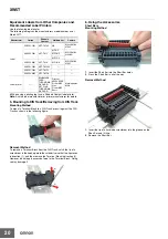
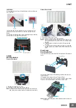
Page 20: ...in direction 1 and then remove the Terminal Block in direction 2 However do not apply excessive force to the Terminal Block Doing so may damage it 6 Using the Accessories Short Bars Mounting Method 1 Insert the Short Bar into the Short Bar holes 2 Press the Short Bar in all of the way Removal Method 1 Insert the tip of a flat blade screwdriver into the groove on the Short Bar and lift it up 2 Remo...

Page 21: ...of the Terminal Blocks Note 1 There is no place to mount the Top surface Labels on Two tier Terminal Blocks with a width of 3 5 mm so they cannot be used 2 Different models of Labels are used for the top and side surfaces 3 If multiple Terminal Blocks of the same type are used side by side you can use multiple Labels still connected to each other End Cover Mounting Method Attach the End Cover to t...

Page 22: ...ks Separator Plate Mounting Method Use a flat blade screwdriver to tighten the screw in the middle of the top surface to mount the Separator Plate Loosen the screw to remove the Separator Plate from the DIN Track 7 Storage Storage Temperature Range 40 to 85 C with no condensation or icing Storage Humidity Range 5 to 95 M4 Screw ...

Page 23: ... CONNECTED WITH THE PRODUCTS WHETHER SUCH CLAIM IS BASED IN CONTRACT WARRANTY NEGLIGENCE OR STRICT LIABILITY Further in no event shall liability of Omron Companies exceed the individual price of the Product on which liability is asserted Suitability of Use Omron Companies shall not be responsible for conformity with any standards codes or regulations which apply to the combination of the Product i...

Page 24: ...L 60169 U S A Tel 1 847 843 7900 Fax 1 847 843 7787 Regional Headquarters OMRON EUROPE B V Wegalaan 67 69 2132 JD Hoofddorp The Netherlands Tel 31 2356 81 300 Fax 31 2356 81 388 Contact www ia omron com Kyoto JAPAN OMRON ASIA PACIFIC PTE LTD No 438A Alexandra Road 05 05 08 Lobby 2 Alexandra Technopark Singapore 119967 Tel 65 6835 3011 Fax 65 6835 2711 OMRON CHINA CO LTD Room 2211 Bank of China Tow...

Reviews: