4
Edit
4-25
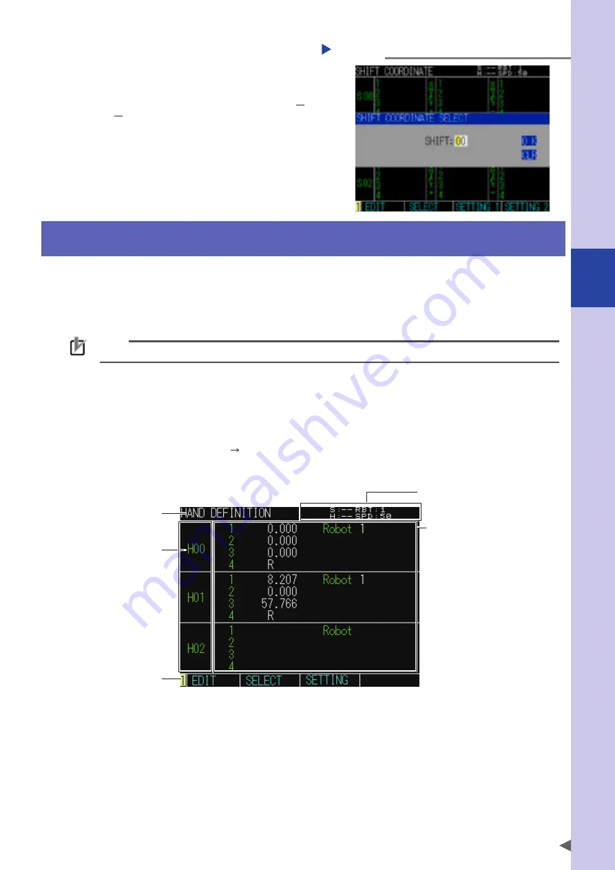
Inputting the shift number
Step 2
Step 2
Input the shift number.
Use 0 to 9 keys to input the shift number.
Select [CLR] and press the ENTER key. The shift
number currently selected at the upper right
portion of the screen changes from (S) to "
" showing that the shift number is not
selected.
Step 3
Set the shift number.
Select [OK], and then press the ENTER key.
Press the ESC key to return to the previous
screen.
4. Hand definitions
Use the cursor keys to select [Edit] on the initial screen and press the ENTER key. Next, select [Hand
Definition] and press the ENTER key to display the "HAND DEFINITION" screen.
In this hierarchy, you can display, edit, or set the hand definitions.
However, when using SCARA type robots, the standard coordinates need to be set. For details about how to
set the standard coordinates, refer to "8. Standard coordinates" in this Chapter.
NOTE
When using multiple robots, the hand data cannot be used commonly.
The tip position of the tool attached to the second arm (Y-axis) or the R-axis can be specified as the robot
coordinate position by hand definition.
There are 4 kinds of hand definitions depending on the combination of the robot type and tool attachment
position.
Using hand definitions allows moving the tips of different tools to positions on the same Cartesian coordinates.
"HAND DEFINITION" screen (Edit Hand Definition) a screen like that shown below appears.
■
"HAND DEFINITION" screen
4. Hand data
2. Robot setting status
5. Guide line
1. Hierarchy
3. Hand number
1.
Hierarchy
Displays the current hierarchy.
Summary of Contents for YRCX Series
Page 1: ...7 6HULHV DW 1R 1 5 5RERW RQWUROOHU 23 5 7 21 0 18 6 5 5RERWV 5 6HULHV...
Page 2: ......
Page 10: ......
Page 12: ......
Page 14: ......
Page 20: ......
Page 28: ......
Page 164: ......
Page 166: ......
Page 178: ......
Page 186: ......
Page 264: ......
Page 265: ......
Page 266: ...DW 1R 1 XWKRUL HG LVWULEXWRU 3ULQWHG LQ XURSH...


