background image

4-12

Sec

tio

n 4

EX
TERN

AL I/O

ZS-L

User’s Manual

Section 4
RS-232C Input/Output

Setting the Communication Specifications

Set the RS-232C communications specifications.
Match the communication specifications of the ZS-L Series to those of the external device.

FUN mode-[SYSTEM]-[COM]

For details on communication protocol, refer to the “Communication Command Reference” (provided
separately). For the Communication Command Reference, please contact your OMRON representative.

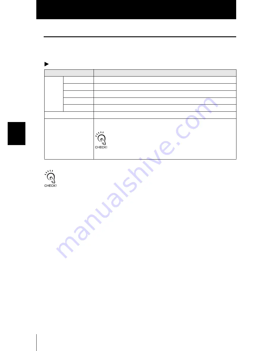
Setting

Range

RS-
232C

LENGTH

8BIT, 7BIT (default value: 8BIT)

PARITY

NON, OFF, EVEN (default value: NON)

STOP

1BIT, 2BIT (default value: 1BIT)

BAUDRAT

9600, 19200, 38400, 57600, 115200 (default value: 38400)

DELIMIT

CR, LF, CR+LF (default: CR)

MODE

CompoWay/F, non-procedural (default: CompoWay/F)

NODE (node No.)

0 to 16

The node No. refers to the connection group No. as seen from the host
device (PLC). Not only the ZS Series but other multiple devices are con-
nected to the PLC. The No. assigned to devices connected to a PLC
such as this is referred to as a node No.

Summary of Contents for ZS-L -

Page 1: ...USER S MANUAL Smart Sensor ZS L Series Ver 2 0 Cat No Z208 E1 02 ...

Page 2: ...Language to English Turn the power ON with the MENU key held down This displays the display language Introduction This manual provides information regarding functions performance and operating methods that are required for using the ZS L Series When using the ZS L Smart Sensor be sure to observe the following The ZS L Smart Sensor must be operated by personnel knowledgeable in electrical engi neer...

Page 3: ...ction 6 User s Manual Smart Sensor 2D CMOS Laser Type ZS L Series APPLICATION CONSIDERATIONS Please Read FEATURES INSTALLATION CONNECTION SETUP EXTERNAL I O APPLICATION SETTING EXAMPLES APPENDIX INTRODUCTION SECTION 1 SECTION 2 SECTION 3 SECTION 4 SECTION 5 SECTION 6 ...

Page 4: ...ALONE HAS DETERMINED THAT THE PRODUCTS WILL SUITABLY MEET THE REQUIREMENTS OF THEIR INTENDED USE OMRON DISCLAIMS ALL OTHER WARRANTIES EXPRESS OR IMPLIED LIMITATIONS OF LIABILITY OMRON SHALL NOT BE RESPONSIBLE FOR SPECIAL INDIRECT OR CONSEQUENTIAL DAMAGES LOSS OF PROFITS OR COMMERCIAL LOSS IN ANY WAY CONNECTED WITH THE PRODUCTS WHETHER SUCH CLAIM IS BASED ON CONTRACT WARRANTY NEGLIGENCE OR STRICT L...

Page 5: ...ems aviation systems medical equipment amusement machines vehicles safety equipment and installations subject to separate industry or government regulations Systems machines and equipment that could present a risk to life or property Please know and observe all prohibitions of use applicable to the products NEVER USE THE PRODUCTS FOR AN APPLICATION INVOLVING SERIOUS RISK TO LIFE OR PROPERTY WITHOU...

Page 6: ...proofreading errors or omissions PROGRAMMABLE PRODUCTS OMRON shall not be responsible for the user s programming of a programmable product or any consequence thereof COPYRIGHT AND COPY PERMISSION This document shall not be copied for sales or promotions without permission This document is protected by copyright and is intended solely for use in conjunction with the product Please notify us before ...

Page 7: ... in serious injury or death Additionally there may be significant property damage Meanings of Alert Symbols Indicates the possibility of laser radiation Indicates prohibition when there is a risk of minor injury from electrical shock or other source if the product is disassembled Indicates general prohibitions for which there is no specific symbol Alert statements in this Manual This product is no...

Page 8: ... power devices 2 Power Supply and Wiring The supply voltage must be within the rated range DC24V 10 Reverse connection of the power supply is not allowed Open collector outputs should not be short circuited Use the power supply within the rated load High voltage lines and power lines must be wired separately from this product Wiring them together or placing them in the same duct may cause inductio...

Page 9: ...nect surge absorbers that suit the operating environment Before turning ON the power after the product is connected make sure that the power supply voltage is correct there are no incorrect connections e g load short circuit and the load current is appropriate Incorrect wiring may result in breakdown of the product Before connecting disconnecting the Sensor Head make sure that the Smart Sensor is ...

Page 10: ...er brush used to clean camera lenses to blow them off Do not blow the dust par ticles with your mouth To remove smaller dust particles wipe gently with a soft cloth for cleaning lenses moistened with a small amount of alcohol Do not use excessive force to wipe off dust particles Scratches on the filter may cause errors 6 Sensing Objects The product sometimes cannot accurately measure the following...

Page 11: ...e approx 500 s default HIGH PRECISION Select this mode to measure workpieces at high precision measurement cycle approx 2 ms HIGH SPEED Select this mode to measure workpieces at high speed measurement cycle max speed approx 110 s HIGH SENSITIVITY Select this mode to measure workpieces with sensitivity set high In this measure ment mode sensitivity to received light is much better than the HIGH PRE...

Page 12: ...en and windows dialog boxes and other GUI elements displayed on the PC are indicated enclosed by brackets aa Visual Aids Indicates points that are important to ensure full product performance such as operational precautions and application procedures Indicates pages where related information can be found Indicates information helpful in operation ...

Page 13: ...s 1 2 ZS L Applications 1 4 Basic Configuration 1 9 Part Names and Functions 1 10 Section 2 INSTALLATION CONNECTION 2 1 About Installation and Connection 2 2 Sensor Controller 2 3 Attaching the ferrite core 2 3 Installing the Sensor Controller 2 4 About the I O cable 2 7 Sensor Head 2 11 Attaching the ferrite core 2 11 Installing the Sensor Head 2 12 Connecting Sensor Heads 2 18 SmartMonitor ZS 2 ...

Page 14: ...18 Setting Average 3 19 Setting Differentiation 3 19 Setting Output Processing of Sensing Information 3 20 Setting Scaling 3 20 Setting Hold Functions 3 24 Setting Zero Reset 3 28 Setting Threshold Values 3 31 Setting the Display Method 3 32 Setting the Digital Displays 3 32 Setting the LCD Display 3 33 HELP 3 34 Setting Banks 3 34 Switching banks 3 34 Clearing banks 3 34 Setting the System Enviro...

Page 15: ...PPLICATION SETTING EXAMPLES 5 1 Measuring the Front Side of Black Sheet Rubber 5 2 Measuring the Height of a PCB Surface 5 5 Measuring the Thickness of Glass 5 7 Section 6 APPENDIX 6 1 Troubleshooting 6 2 Error Messages and Countermeasures 6 3 Q A 6 5 Glossary 6 6 Specifications and External Dimensions 6 7 Sensor Head 6 7 Sensor Controller 6 18 Panel Mount Adapters 6 20 RS 232C Cable for Connectin...

Page 16: ...14 CONTENTS ZS L User s Manual READ AND UNDERSTAND THIS DOCUMENT CONTENTS Linearity Characteristic by Materials 6 33 Version Up Information 6 42 INDEX 6 43 Revision History 6 47 ...

Page 17: ...Section 1 FEATURES 1 1 ZS L User s Manual Section 1 FEATURES ZS L Features 1 2 ZS L Applications 1 4 Basic Configuration 1 9 Part Names and Functions 1 10 ...

Page 18: ... handy 1 Compact Sensor Head A 2D CMOS image sensor proprietary algorithms and other sensing technology are incorporated in the compact Sensor Head This achieves an improved dynamic range high speed sampling up to 110 µs and a high resolution 2 An Enhanced Lineup of Sensor Heads Regular Reflection Type Diffuse Reflection Type ZS LD20T ZS LD40T ZS LD50 ZS LD80 ZS LD200 Measurement distance 20 1 mm ...

Page 19: ...lity The Sensor Controller supports various workpieces which means that detailed and flexible settings can be made Incorporates extensive functions such as Filter and Hold to support a wide range of applications Mutual interference from 2 adjacent Sensor Heads can be prevented by shifting the timing of laser beam emission List of Setting Items p 3 9 5 USB Connection The Sensor Controller is provid...

Page 20: ...ght Detection of light penetrating workpieces such as PCBs Proprietary sensing algorithms enable the detection of workpieces through which light penetrates Detection of transparent workpieces such as glass Proprietary sensing algorithms enable the detection of workpieces through which light passes through Up to 3 sheets of glass can be detected which means that the glass thickness and gap between ...

Page 21: ...rious measurement information can be displayed on the sub display lower section on the Sensor Controller LCD screens can be customized to change the display of desired information to easier to understand terminology H LD ON ZERO ENABLE P L MAIN MESURE SUB THRESH EQPNo OMRON_1UNIT Threshold value Voltage current value Present value Received light amount Resolution Switches various mea surement info...

Page 22: ...the thickness of glass and GAP for measuring the gap between glass are provided as sensing object options Just selecting these options allows you to set measurement conditions simply Setting the Measurement Object p 3 14 Mutual Interference Prevented Mutual interference between 2 Sensor Heads can be prevented by shifting the laser beam emission timing Setting Prevention of Mutual Interference p 3 ...

Page 23: ...extended up to 22 m to suit your setup environment Only the ZS XC_B R cable allows this extended connected Note however that the connection with the ZS XC_A cannot be extended The cable may break at locations when it is made to bend So use the robot cable type Extension Cable ZS XC5BR DIN track Panel H LD ON ZERO ENABLE P L H LD ON ZERO ENABLE P L ZS LD Sensor cable ZS LD Sensor cable ZS LDC ZS LD...

Page 24: ...nagement Measurement conditions can be set up and settings saved read or copied Real time verification of changes in detection workpiece height The measurement conditions can be changed while verifying the measurement state by a waveform The screen show here may differ from the actual screen The screen shown here may differ from the actual screen ...

Page 25: ...a USB port SmartMonitor ZS cannot be used on the RS 232C interface Communication using CompoWay F or non procedural protocol is possible 1 SmartMonitor ZS Professional option software sold separately ZS SW11E Sensor Head Extension Cable Sensor Controller ZS LDC11 LDC41 Performs measurement and outputs measurement results Power Supply DC24V 10 Recommended parts 1 When 1 Sensor Controller is connect...

Page 26: ...n measurement is not possible e g when the received light amount is excessive or insufficient when the measuring range is exceeded when the Sensor Head is not con nected or when measurement is not being performed in the FUN mode 4 Main Display The Main Display shows measured values 5 Sub display The sub display shows thresholds and additional information during measurement H LD ON ZERO ENABLE P L ...

Page 27: ...indicator is lit when the condition measured value LOW threshold is satis fied 11 PASS indicator The PASS indicator is lit when the condition LOW threshold measured value HIGH threshold is satisfied 12 HIGH indicator The HIGH indicator is lit when the condition HIGH threshold measured value is sat isfied 13 Sensor Head connector This connector connects the Sensor Head 14 Coupler This connector is ...

Page 28: ...e between the front of the Sensor Head and workpiece Both NEAR and FAR indicators are lit Measuring center distance measuring range x 10 NEAR indicator is lit Near side within measuring range FAR indicator is lit Far side within measuring range NEAR and FAR indicators are flashing Outside measuring range These indicators also function as laser alarm indicators At least either of these indicator li...

Page 29: ...ensor Controller 2 3 Attaching the ferrite core 2 3 Installing the Sensor Controller 2 4 About the I O cable 2 7 Sensor Head 2 11 Attaching the ferrite core 2 11 Installing the Sensor Head 2 12 Connecting Sensor Heads 2 18 SmartMonitor ZS 2 19 Installing SmartMonitor ZS on a personal computer 2 19 Starting up SmartMonitor ZS 2 23 ...

Page 30: ...ing of this manual and check the installa tion environment Checking the installation site Read Precaution for Correct Use at the beginning of this manual and check the installation site About the power supply Before installing and connecting the Smart Sensor be sure to turn it OFF Also read Precaution for Safe Use and Precaution for Correct Use at the beginning of this manual and check the power s...

Page 31: ...f the I O cable Before connecting disconnecting peripheral devices make sure that the Sensor Controller is turned OFF The Sensor Controller may break down if the Sensor Controller is connected or disconnected while the power is ON Attaching the ferrite core Attach the ferrite core provided with the Sensor Controller to the input output cable of the Sensor Controller Ferrite core ...

Page 32: ...wn until you hear it snap into place Always hook the connector end of the Sensor Controller on the DIN track first Hooking the I O cable end on the DIN track first may impair the mounting strength of the DIN track attachment Removal procedure The following describes how to remove the Sensor Controller from the DIN track 1 Pull the hook on the I O cable end of the Sensor Controller downwards 2 Lift...

Page 33: ...ontroller from the rear of the panel towards the front 2 Install the small Mount Adapters on the four holes on the Sensor Controller 3 Install the long Mount Adapters on the two holes on the small Mount Adapter H LD ON ZE RO EN AB LE P L H LD ON ZE RO EN AB LE P L Panel H LD ON ZE RO EN AB LE P L H LD ON ZE RO EN AB LE P L Panel Mount Adapter Panel Mount Adapter H LD ON ZE RO EN AB LE P L H LD ON ...

Page 34: ...pters attached onto the panel from the front Take care not to pinch the I O cable 5 Hook the hooks of the mounting fixture onto the two holes of the smaller Mount Adapters and tighten the screws 6 Make sure that the Sensor Controller is firmly fixed on the panel H LD ON ZE RO EN AB LE P L H LD ON ZE RO EN AB LE P L Panel Mounting fixture ...

Page 35: ...r devices Wiring them together or placing them in the same duct may cause induction resulting in malfunction or damage 2 GND The GND terminal is the 0V power supply terminal When using a Sensor Controller with an NPN output the GND terminal is also the common I O terminal for all I O except for the linear output 3 OUT0 HIGH output This outputs judgment results HIGH 4 OUT1 PASS output This outputs ...

Page 36: ... 9 Signal When Standard is selected default When Bank is selected IN0 External trigger timing input Bank input A IN1 Reset input Bank input B IN2 LD OFF input LD OFF input IN3 Zero reset input Zero reset input Signal Name Description External trigger timing input This timing input is for signal input from external devices Use it for hold function timing Reset input This resets all executing measur...

Page 37: ...k Pink Gray Co axial black Shielded Load Load Load Load Load Load DC24V OUT0 OUT1 OUT2 OUT3 OUT4 GND 0V DC24V Yellow Light blue Purple White IN0 IN1 IN2 IN3 Orange Linear output Linear GND Current output 300Ω or less Voltage output 10 kΩ or more Current voltage output selector switch Current output 4 to 20 mA Internal circuits Voltage output 10 V 40 Ω ...

Page 38: ... Red Green Black Pink Gray OUT0 OUT1 OUT2 OUT3 OUT4 Blue GND 0V Yellow Light blue Purple White IN0 IN1 IN2 IN3 Orange Load Load Load Load Load Co axial black Shielded Linear output Linear GND Load Current output 300 Ω or less Voltage output 10 kΩ or more Current voltage output selector switch Current output 4 to 20 mA Voltage output 10 V 40Ω ...

Page 39: ...h ends of the Sensor Head cable If the ferrite core comes loose from the cable fasten the ferrite core in place with the Insure Lock supplied Never look into the laser beam Doing so continuously will result in visual impairment Never look into the laser beam Do not disassemble the product Doing so may cause the laser beam to leak resulting in the danger of visual impairment Do not disas semble the...

Page 40: ...can be minimized by installing the Sensor Head with the line formed by the emission and reception axes parallel to the boundary line on the workpiece as fol lows Installing near walls Measurement error occurs when the Sensor Head receives light reflected from walls If a sufficient distance cannot be maintained between the Sensor Head and the wall measurement error can be reduced by installing the ...

Page 41: ...asuring stepped workpieces you can minimize the influence caused by the different levels of the workpiece by installing the Sensor Head with the line formed by the emission and reception axes parallel to the step face Rotating objects When measuring rotating workpieces you can minimize the influence caused by vibra tion of the rotating object and positional shift by installing the Sensor Head with...

Page 42: ...ead Adjusting mutual interference When using two or more Sensor Heads next to each other mutual interference will not occur if other beam spots are outside the shaded areas in the following diagrams ZS LD20T LD20ST ZS LD40T 3 5 2 1 5 4 3 5 18 22 unit mm 3 5 6 2 35 45 4 unit mm ...

Page 43: ...Section 2 INSTALLATION CONNECTION Section 2 Sensor Head 2 15 ZS L User s Manual ZS LD50 LD50S ZS LD80 2 5 2 11 9 5 42 59 4 unit mm 2 41 13 2 18 61 102 6 unit mm ...

Page 44: ...2 16 Section 2 INSTALLATION CONNECTION ZS L User s Manual Section 2 Sensor Head ZS LD130 ZS LD200 165 22 3 107 107 12 8 14 5 58 unit mm 3 133 20 4 36 142 275 10 unit mm ...

Page 45: ...Section 2 INSTALLATION CONNECTION Section 2 Sensor Head 2 17 ZS L User s Manual ZS LD350S 11 84 201 201 590 389 45 26 15 30 201 unit mm ...

Page 46: ...or Controller is connected or disconnected while the power is ON Connecting the Sensor Head Insert the Sensor Head connector into the Sensor Controller until it locks in place Disconnecting the Sensor Head Pull out the Sensor Head while pressing in the hooks on both sides of the Sensor Head connector Do not touch the terminals inside the connector All settings on the Sensor Controller will be clea...

Page 47: ...ore you install SmartMonitor ZS quit all other programs that are running If virus detection soft ware is enabled installation may take time to complete Log on as an Administrator or a user with system access rights 1 Turn your PC ON and startup up Windows 2 Insert your SmartMonitor ZS CD ROM into the CD DOM drive on your personal computer 3 Auto run automatically displays the installation screen F...

Page 48: ...onwards the USB driver is automat ically recognized and does not need to be re installed To install the USB driver log on as an Administrator or a user with system access rights Install SmartMonitor ZS before installing the USB driver The error message Failed to pass the Windows logo test is sometimes displayed at installation Press the Continue button to continue with the installation 1 Turn your...

Page 49: ...sk recommended radio button and click the Next button 5 Mark the CD ROM drive checkbox and click the Next button If the Sensor Controller is not automatically detected click the Browse button and select USB folder on the CD ROM To install on a personal computer not equipped with a CD ROM drive select the Program Files OMRON SmartMonitorZS usb folder ...

Page 50: ...ke sure that the optimum driver has been detected and click the Next button Installation begins When installation ends the completion message is displayed 7 Click the End button The same screen in step 2 is displayed Repeat the above procedure This completes installation of the USB driver ...

Page 51: ...ws Start menu When the connection between the personal computer and Sensor Controller cannot be established Check the COM port No assigned on the personal computer in Device Manager 1 Right click My Computer on the Windows desktop and click Properties 2 Click Device Manager D on the Hardware tab 3 Open Port COM LPT and check which number COM in OMRON Smart Sensor USB COM is set to 4 Set this COM p...

Page 52: ...2 24 Section 2 INSTALLATION CONNECTION ZS L User s Manual Section 2 SmartMonitor ZS ...

Page 53: ...n 3 18 Setting Smooth 3 18 Setting Average 3 19 Setting Differentiation 3 19 Setting Output Processing of Sensing Information 3 20 Setting Scaling 3 20 Setting Hold Functions 3 24 Setting Zero Reset 3 28 Setting Threshold Values 3 31 Setting the Display Method 3 32 Setting the Digital Displays 3 32 Setting the LCD Display 3 33 HELP 3 34 Setting Banks 3 34 Switching banks 3 34 Clearing banks 3 34 S...

Page 54: ...d Set the threshold value for judging measured values After you have made or changed settings be sure to save the setup data All settings will be deleted if you turn the power OFF without saving the data Set the Sensor Head and Sensor Controller in place and connect the personal computer Installation and Connection Set how measured values are to be output External I O Setting scaling Setting hold ...

Page 55: ...the System Environment Setting the Display Method Set what is to be displayed on the Sensor Controller during measurement in the RUN mode Applied Use of Functions Additional Functions Switching banks Clearing banks Setting the digital displays Setting the LCD screen Help Initializing setup data Checking sensor controller information Setting key lock Setting the sensor load method Setting Zero Rese...

Page 56: ... The ZS L Series has the following 3 operating modes Switch to the desired mode before you start operation To switch the operating mode use the Mode Switch When you switch the operating mode after changing the measurement conditions you will be prompted to save the settings Save the settings as required If you turn off the Sensor Controller without saving these settings the newly set measurement c...

Page 57: ...the LEFT or RIGHT key Key Operations Key FUN Mode Function keys Directly sets the No preceding the items displayed on the LCD screen LEFT key RIGHT key The function changes depending on the settings Scrolls pages in list menus Selects the digit of numerical values UP key DOWN key Changes numerical values during input A B C D E F G H I J K L M N O P Q R S T U V W X Y Z Main Display LCD screen Sub d...

Page 58: ...y selected No is displayed flash ing 3 Press function key 2 representing HI RESO The Complete message is displayed 4 Press the MENU key to return to the top menu Pressing the ESC key returns to the previous menu MENU key Displays the top menu of the FUN mode SET key Applies the item you are setting up ESC key Returns to the previous menu Key FUN Mode 1 SENSING 3 OUTPUT 2 FILTER 1 MODE 3 GAIN 2 SET...

Page 59: ...reference values only These values differ from actual linear output values RESOLU Displays the fluctuation width peak to peak of the measured value over a fixed amount of time BRIGHT Displays the current received light amount The current emitted light amount also is displayed on the LCD upper section DISTANCE Displays the measured value before it is processed by hold or other functions Key Measure...

Page 60: ...the display customize menu SET key Executes a zero reset Applies numerical value settings ESC key Hold down for at least two sec onds to cancel a zero reset Returns to the previous menu When the top menu is displayed returns to the measured value display Key TEACHIMG DIRECT IN Function keys Not used Not used LEFT key RIGHT key Not used Selects the digit in the threshold numerical value UP key DOWN...

Page 61: ...1 to 80 p 3 13 OBJECT NORMAL NORMAL PCB MIRROR GLASS THICK GAP p 3 14 SYNC OFF OFF ON timing A timing B p 3 16 GAIN 1 1 to 5 p 3 17 Measurement area setting 1 Measurement level setting 1 FILTER SMOOTH ON OFF ON p 3 18 AVERAGE 128 1 2 4 8 16 32 64 128 256 512 1024 2048 4096 p 3 19 DIFF OFF OFF ON p 3 19 OUTPUT SCALING OFF OFF ON AUTO MAN p 3 20 HOLD TYPE OFF OFF PEAK BOTTOM P P AVERAGE SAMPLE p 3 2...

Page 62: ...N1 ON OFF ON IN2 ON OFF ON IN3 ON OFF ON I O SET IN NORMAL NORMAL BANK p 4 7 DIGITAL ON OFF ON BANK CHANGE BANK1 BANK1 BANK2 BANK3 BANK4 p 3 34 CLEAR Initializes bank settings p 3 34 SYSTEM SAVE Saves Sensor Controller settings p 3 35 INIT Initializes Sensor Controller settings p 3 35 INFO CYCLE Displays the current measurement cycle p 3 36 VERSION Displays the Sensor Controller version COM RS 232...

Page 63: ... 3 digits 3rd in the case of the ZS LD50 80 200 and 4 digits 4th in the case of the ZS LD20T 40T TEACH mode This is the mode for setting the threshold values Settings Default Value Option Setting Range Pages DIGITAL DOT 3 0 to 5 p 3 32 ECO NORMAL NORMAL ECO OFF p 3 32 LCD ON OFF ON ON AUTOOFF OFF p 3 33 B LIGHT ON ON AUTOOFF OFF p 3 33 CUSTOM U OFF L OFF U ON OFF L ON OFF U CUSTM L CUSTM p 3 33 HE...

Page 64: ...nsitivity set high measure ment cycle approx 2 ms HI SPEED Select this mode to measure workpieces at high speed measurement cycle max speed approx 110 µs HI SENS Select this mode to measure workpieces with sensitivity set high In this measurement mode sensitivity to received light is much better than the HIGH PRECISION mode as the sampling time is longer measurement cycle approx 4 ms CUSTOM EXPOSE...

Page 65: ...escription DIFFUSE Select this item when the Sensor Head is installed for diffuse reflection sensing REGULAR Select this item when the Sensor Head is installed for regular reflection sensing Setting Description AUTO Automatically adjusts the emitted light amount according to the reflection factor of the workpiece Note that the response time varies with each mea surement default value RANGE UPPER L...

Page 66: ...thickness between 1 and 2 FILM Select this to measure the thickness of glass with a film coating Measures the thickness of the glass having different reflection factors on the front side 1 and the backside 2 such as backside deposited glass STOP Select this to measure the thickness of still workpieces MOVE Select this to measure the thickness of moving workpieces GAP NORMAL Select this to measure ...

Page 67: ...r limit of the auto range for the amount of emitted light When measurement cannot be performed normally adjust the upper and lower limits of the auto range for the amount of emitted light The mutual interface prevention function does not operate at this setting MOVE Thickness and gap can be measured stably at high speed by dividing the measurement area into separate sections for each plane to meas...

Page 68: ... influenced by other settings Check the current measurement cycle by FUN Mode SYSTEM INFO CYCLE The same sensing mode must be set to each controller when the mutual interference prevention mode is used When HI SPEED or CUSTOM is selected as the measurement mode the same con ditions must be set Setting different conditions will result in a different measurement cycle on each controller and mutual i...

Page 69: ...ction so that even workpieces having an extremely low amount of reflected light or workpieces having a large tilt can be measured stably The measurement resolution sometimes drops when a large gain is set FUN Mode SENSING GAIN Setting Description 1 2 3 4 5 Adjusts the internal gain of the CMOS image sensor default value 1 1 gain small 5 gain large ...

Page 70: ...e spiking FUM Mode FILTER SMOOTH Setting Description OFF The smooth function is not used ON The intermediate value of the past 15 measured values is set as the measurement result at each measurement cycle default value 0 Waveform when filter function is not set Displacement Smooth Displacement SMOOTH Average value Differentiation Spike like changes are removed Changes are smoothed out Changes are ...

Page 71: ...ime The differentiation function detects changes between the present value and the measured value that is in effect just before the comparing pitch The coefficient of this comparing pitch is defined as the differentiation cycle Example Differentiation cycle 10 ms FUN Mode FILTER DIFF Setting Description 1 2 4 8 16 32 64 128 256 512 1024 2048 4096 Sets the average count default value 128 Setting De...

Page 72: ...tting of correction values and one point scaling and two point scaling that automatically set the correction values of a placed sensing object The settings listed below return to the default settings when scaling is set Set these items after scaling settings have been completed Zero Reset Setting One point Scaling Measurement is performed at one position and offset values are set for that measure ...

Page 73: ...int of the scaling setting The position of the decimal point on the display follows the DOT setting of the dis play setup in the RUN mode 4 Press the SET key to apply the setting 5 Press the SET key without entering any value for the second point 6 Select FORWARD or INVERS FORWARD The larger the distance between the Sensor Head and the sensing object the larger the measured value displayed on the ...

Page 74: ...rement range for the connected Sensor Head Example For the ZS LD80 diffuse reflection type The two measured points must be separated by at least 30 mm x 0 01 0 3 mm as the measuring range is 30 mm 15 mm FUN Mode OUTPUT SCALING ON AUTO 1 Set the first point by following steps 1 to 4 of the one point scaling procedure 80 78 68 67 67 80 Display value mm Actual measured value mm Sensor Head Actual dis...

Page 75: ...s 3 Press the SET key to apply the setting Manual Setting Enter numerical values for scaling correction values FUN Mode OUTPUT SCALING ON MANUAL Setting Description SPAN Sets the inclination of the sensor characters as a coefficient Range 2 0 to 2 0 OFFSET Adds subtracts a fixed value to or from the measured value Range 999 99 to 999 999 INPUT POINT 2 VAL SET OK DIG Measurement value mm Workpiece ...

Page 76: ...ue during the sampling period The output changes at the end of the sampling period and is held until the end of the next sam pling period P P Holds the difference between the maximum and minimum values during the sampling period This option is selected mainly when detecting vibra tion The output changes at the end of the sampling period and is held until the end of the next sampling period AVERAGE...

Page 77: ...end after the specified sampling period has elapsed SELF UP The sampling period is the period that the measured value is greater than the specified self trigger level Hold measurement is possible without a sync input When SELF UP is selected the following items are subsequently displayed TRG LEVEL Sets the desired self trigger level Range 999 99 to 999 999 TRG HYS Sets the hysteresis width for the...

Page 78: ...ld measurement is possible without a sync input When SELF DOWN is selected the following items are subsequently dis played TRG LEVEL Sets the desired self trigger level Range 999 99 to 999 999 TRG HYS Sets the hysteresis width for the self trigger Range 0 to 999 999 When a delay time is set the timing when the measured value becomes greater than the self trigger level and the end of the sam pling ...

Page 79: ...OUTPUT HOLD DELAY Setting Description OFF The delay time is not set default value ON Sets the delay time When ON is selected the following items are subsequently displayed T DELAY Sets the delay time Range 0 to 5000 ms T TIME Sets the sampling time Range 1 to 5000 ms Set so that the delay time sampling time is less than the timing input ON interval If the next timing input for measurement is recei...

Page 80: ...ut as the measured value Example 2 Using the height of sensing object as the measured value with an offset set to 10 Example 3 Using zero reset to measure steps in sensing object zero reset at each measurement To execute a zero reset Press the SET key in the RUN mode To cancel a zero reset Hold down the ESC key for at least two seconds in the RUN mode Timing chart when inputting the zero reset sig...

Page 81: ...t the reference value for zero reset to a value other than 0 FUN Mode OUTPUT 0 RESET OFFSET Setting Description REAL Sets the measured value when a zero reset is executed to zero default value HOLD Sets the measured value hold value when a zero reset is executed to zero This setting is enabled when hold measurement is performed Setting Description OFFSET Sets the reference value Range 999 99 to 99...

Page 82: ... enabled If zero reset memory is enabled the zero reset level data will be written in the Sensor Controller non volatile memory EEPROM at each zero reset The EEPROM can be written a maximum of 100 000 times Writing the zero reset level for each measurement can therefore use up the life of the memory and lead to malfunctions Even if zero reset memory is enabled the zero reset level will be held als...

Page 83: ... ZS L Series Controllers TEACH Mode Method Details TEACHING MENU key Performs measurement and uses the measurement results to set threshold values Teaching is useful when threshold samples i e with the upper and lower limits can be obtained beforehand Hold trigger and scaling settings that have been made before teaching are reflected in the teaching measurements DIRECT IN L R UP DOWN keys The thre...

Page 84: ... display and sub display When five or less digits are set the digits are disabled from the rightmost digit first RUN Mode MENU key DIGITAL DOT Setting the ECO display Set the brightness of the main display and sub displays RUN Mode MENU key DIGITAL ECO Setting Description 5th 4th 3rd 2nd 1st 0 Sets the number of display digits past the decimal point default value 3rd when the ZS LD50 80 200 is con...

Page 85: ...r that pressing the MENU key displays the display customize menu Setting Description ON Turns the LCD screen backlight ON at all times default value AUTOOFF Turns the backlight OFF when no operations are performed for one minute OFF Turns the LCD screen backlight OFF Setting Description UPPER Set this item to ON to display characters set at U CUST on the upper section of the LCD screen default U O...

Page 86: ...ank Switching banks Bank 1 is selected as the default Banks 2 and 4 are also available Banks can be switched from an external device by communication commands For details on command formats refer to the Communication Command Reference provided sepa rately FUN Mode BANK CHANGE Clearing banks Clearing initializes the settings of the currently selected bank FUN Mode BANK CLEAR Settings in SYSTEM and ...

Page 87: ...l be deleted if you turn the power OFF without saving the data A message prompting you to save data will be dis played if you change a mode without saving data after you have changed settings FUN Mode SYSTEM SAVE Initializing setup data Return all bank settings and system settings to their factory settings The settings of all banks and system settings are initialized regardless of the currently se...

Page 88: ...t whether or not to load information from the currently connected Sensor Head when the Sensor Controller is started up FUN Mode SYSTEM Sen INFO Setting Description CYCLE Displays the current measurement cycle INFO Displays the version of the Sensor Controller system Setting Description OFF Cancels the key lock function default value ON Turns the key lock function ON Setting Description LOAD Reads ...

Page 89: ...ystem Environment 3 37 ZS L User s Manual Setting the display language Set the display language of the LCD screen FUN Mode SYSTEM LANGUAG Setting Description Japanese Displays menus in Japanese default value English Displays menus in English ...

Page 90: ...3 38 Section 3 SETUP ZS L User s Manual Section 3 Setting the System Environment MEMO ...

Page 91: ...ar Input Output 4 2 Setting Linear Output 4 2 Setting Judgment Output 4 5 Non Measurement Settings 4 6 Input Signal Settings 4 7 I O Assignment Settings 4 7 Timing Charts 4 9 RS 232C Input Output 4 11 RS 232C Specifications 4 11 Setting the Communication Specifications 4 12 ...

Page 92: ...ship between displayed measured values and output values can be set freely Match the settings to suit the connected external device Enter the output values for any two current values or voltage values to set the output range default value OFF Example Setting 70 mm to 4 mA and 90 mm to 20 mA for current output Separate the two specified points by at least 1 of the rated measuring range for the conn...

Page 93: ...yed on the sub dis play 4 Press the SET Key to apply the setting 5 Set point 2 in the same way as point 1 If the points are not set correctly check the following Is the measured value set on the sub display within the measuring range with scaling and calcula tion settings reflected if set Are the first and second measured points separated by at least 1 of the rated measuring range Are the current ...

Page 94: ...lect either current or voltage output beforehand Also connect the lin ear output to an external ammeter or voltmeter FUN mode I O SET ANALOG ADJUST ON 1 Set the output value of point 1 The output value is displayed on the main display 2 Press the SET Key to apply the setting 3 Set the correction value for point 1 The measurement value is displayed on the sub dis play Adjust the correction value on...

Page 95: ... DELAY After the measurement result has been applied delays turning OFF the PASS output for the time set to the timer Also delays turning ON the HIGH and LOW outputs for the time set to the timer Range 1 to 5000 ms ON DELAY After the measurement result has been applied delays turning ON the PASS output for the time set to the timer Also delays turning OFF the HIGH and LOW outputs for the timer tim...

Page 96: ...er Neither the HIGH nor the LOW output is output Range 1 to 5000 ms Setting Outputs Judgment output Linear output KEEP The status immediately before measurement is stopped is held and output CLAMP default value All OFF Outputs the set CLAMP value At current output 4 12 mA 20 mA MAX approx 25 mA default value MIN approx 2 mA At voltage output 10V 0V 10V MAX approx 11 V default value MIN approx 11 V...

Page 97: ...SET IN For bank inputs A and B the bank can be selected in the following combinations Bank switching is begun 0 5 seconds after the input state changes At most it takes about 30 seconds to switch banks During bank switching the BUSY output becomes ON Setting Description IN0 IN1 IN2 IN3 OFF The input wire is regarded as active when it is OFF ON The input wire is regarded as active when it is ON Set...

Page 98: ...es the measurement cycle When a measurement mode other than High or Custom is selected this digital output setting does not cause the measurement cycle to change FUN mode I O SET I O SET DIGITAL Setting Description OFF Of the communication commands the command FlowDATA for high speed batch acquisition of data is disabled When High is selected for the measurement mode this setting automatically tur...

Page 99: ... OFF ON OFF ON OFF ON Zero reset input Zero reset input Zero reset input Judgment output Judgment output Zero reset setting cancel time Settable pulse width 200 to 800 ms Cancelable pulse width 1000 ms or more Response 5ms Response 1000ms Response at execution of zero reset Response at cancellation of zero reset average count 1 Reset input ON OFF Judgment output Response 3ms OFF ON Response of res...

Page 100: ... O ZS L User s Manual Section 4 Linear Input Output LD OFF input Linear output also is almost the same response time as judgment output ON OFF LD OFF input Emitted light pulse Response time 5 ms OFF ON Response at LD OFF input ...

Page 101: ...e provided separately SmartMonitor ZS cannot be used on the RS 232C interface To use SmartMonitor ZS connect the Sen sor Controller to the personal computer with the USB cable RS 232C Specifications Connector pin assignments An exclusive connector is used for the connector An RS 232C cable compatible with the exclusive connector is provided Recommended part ZS XRS2 cable length 2 m Sensor Controll...

Page 102: ...ation Command Reference please contact your OMRON representative Setting Range RS 232C LENGTH 8BIT 7BIT default value 8BIT PARITY NON OFF EVEN default value NON STOP 1BIT 2BIT default value 1BIT BAUDRAT 9600 19200 38400 57600 115200 default value 38400 DELIMIT CR LF CR LF default CR MODE CompoWay F non procedural default CompoWay F NODE node No 0 to 16 The node No refers to the connection group No...

Page 103: ...ICATION SETTING EXAMPLES 5 1 ZS L User s Manual Section 5 APPLICATION SETTING EXAMPLES Measuring the Front Side of Black Sheet Rubber 5 2 Measuring the Height of a PCB Surface 5 5 Measuring the Thickness of Glass 5 7 ...

Page 104: ...nstalled for regular reflection measurement if the amount of received light is little for example due to the rubber sheet having a glossy surface Adjust the angle of the Sensor Head while verifying the amount of received light on the controller s sub display so that the amount of received light reaches close to 1000 Installing the Sensor Head p 2 12 FUN Mode SENSING MODE 2 Select the sensing mode ...

Page 105: ...SENSING OBJECT 4 Select NORMAL as the type of measurement object Setting the Measurement Object p 3 14 FUN Mode FILTER SMOOTH 5 Set the Filter Function SMOOTH ON AVERAGE 4 times Setting the average count to a low number will result in a more accurate trace of the state of the workpiece surface Setting Average p 3 19 FUN Mode SYSTEM SAVE 6 The save confirmation message is displayed Select OK Save t...

Page 106: ...le differences in the amount of received light You can confirm whether or not there are jumps in the waveform by displaying the waveform in a clamped state Non Measurement Settings p 4 6 FUN Mode SYSTEM SAVE 9 The save confirmation message is displayed Select OK Save the settings to Sensor Controller internal mem ory RUN mode 10 Check for jumps in the waveform by using the graphic display on Smart...

Page 107: ...uch as a PCB through which the laser beam passes through and the reflected light does not form a normal distribution 1 Install the Sensor Head FUN Mode SENSING MODE 2 Select the sensing mode Select the sensing mode taking the content of mea surement to give priority into consideration NORMAL and HI SENS are best suited for the mea surement of PCBs Setting the Measurement Mode p 3 12 1 STAND 3 HI S...

Page 108: ...ion Select DIFFUSE Setting the Head Installation p 3 13 FUN Mode SENSING OBJECT 4 Select PCB as the type of measurement object Setting the Measurement Object p 3 14 FUN Mode SYSTEM SAVE 5 The save confirmation message is displayed Select OK Save the settings to Sensor Controller internal mem ory 1 DIFFUSE 2 REGULAR 1 NORMAL 3 MIRROR 2 PCB Save the data 1OK 2CANCEL ...

Page 109: ...r Head Select installation for regular reflection measurement Installing the Sensor Head p 2 12 FUN Mode SENSING MODE 2 Select the sensing mode Select the sensing mode taking the content of mea surement to give priority into consideration NORMAL and HI SENS are best suited for the mea surement of glass thickness Setting the Measurement Mode p 3 12 Top side 1 Rear side 2 Thickness measurement Raw g...

Page 110: ... Select REGULAR Setting the Head Installation p 3 13 FUN Mode SENSING OBJECT THICK 4 Select NORMAL as the type of measurement object Setting the Measurement Object p 3 14 FUN Mode SYSTEM SAVE 5 The save confirmation message is displayed Select OK Save the settings to Sensor Controller internal mem ory 1 DIFFUSE 2 REGULAR 1 NORMAL 2 FILM Save the data 1OK 2CANCEL ...

Page 111: ...leshooting 6 2 Error Messages and Countermeasures 6 3 Q A 6 5 Glossary 6 6 Specifications and External Dimensions 6 7 Laser Safety 6 23 Requirements from Regulations and Standards 6 24 Engineering Data 6 33 Version Up Information 6 42 INDEX 6 43 Revision History 6 47 ...

Page 112: ...on the bottom of the Sensor Control ler set to the correct position Has the correct selection voltage current been made in the focus settings Linear output levels can be fine tuned p 1 10 p 4 2 The main display remains on Has a timing input been made while the hold function is enabled and the trigger type has been set to EXT If the hold function is enabled and the trigger type is SELF UP or SELF D...

Page 113: ...nt is fixed set to AUTO Bright Error Saturated received light amount from the workpiece Distance measurement error Change decrease the gain setting Change the mode to HIGH SPEED When the emitted light amount is fixed set to AUTO Measure Error When NORMAL PCB MIR ROR is set for the measurement target the number of surfaces currently being measured is 2 or more Change the mode to GLASS Use SmartMoni...

Page 114: ...ils Cause Countermeasure LCD upper sec tion Disp range error The measurement result exceeds the number of dis played digits Change the decimal point digit setting p 3 32 Main Display The sensor is standing by for measurement When hold is set start sam pling and apply the hold value ...

Page 115: ...ing has been executed the distance between the measured values for the two points is not 1 or more of the rated measuring range p 3 20 When focusing is executed an error appears and settings cannot be made Monitor focus settings cannot be made when the distance between the two specified points is not 1 or more of the rated measuring range p 4 2 Is warm up operation still required even if LD OFF in...

Page 116: ...n tains a linear relationship to the displacement of the sensing object i e it shows the accuracy of the linear output Linear output The linear output is output from the linear output line Either current or voltage output can be selected The linear output is made based on the display value and focus settings The actual value output the output value can be displayed on the sub display by pressing t...

Page 117: ...56 4 5 2 2 M 4 45 Reference surface Connector Note 1 ZS LD20T LD20ST L 20 A 45 ZS LD40T L 40 A 32 35 30 15 30 30 1 L Note 1 Mounting hole dimensions Light receiver A Note 1 Reception axis Light emitter Measurement center 4 27 1 Range indicator Emission axis 2 4 5 mounting hole 56 0 1 56 0 1 Vinyl insulated round cable 6 2 mm dia Standard length 0 5 m 2 m Unit mm ...

Page 118: ...ion Diffuse reflection Regular reflection Diffuse reflection Measuring center distance 20 mm 6 3 mm 20 mm 6 3 mm 40mm 30mm Measuring range 1mm 1mm 1mm 1mm 2 5mm 2mm Light source Visible semiconductor laser wavelength 650 nm 1 mW max JIS Class 2 6 Beam diameter 1 25 x 900 µm 25 µm 35 x 2000 µm Linearity 2 0 1 F S Resolution 3 0 25 µm 0 4 µm Temperature charac teristic 4 0 04 F S C 0 02 F S C Sampli...

Page 119: ...3 2 30 3 6 3 77 8 4 7 37 6 15 3 73 2 30 3 19 3 56 4 2 M4 45 2 2 5 3 0 20 Mounting hole dimensions Reception axis Measurement center Emission axis Unit mm 38 4 69 3 69 3 38 4 30 58 4 15 2 73 9 4 6 11 882 41 7 1 6 3 2 2 M 4 2 4 5 Mounting hole Mounting hole dimensions Reception axis Measurement center Emission axis Unit mm ...

Page 120: ... Note 1 ZS LD50 LD50ST L 50 A 25 ZS LD80 L 80 A 15 ZS LD130 L 130 A 12 ZS LD200 L 200 A 8 ZS LD350S L 350 A 5 35 11 15 30 30 1 L Note 1 Mounting hole dimensions Light receiver A Note 1 Reception axis Light emitter Measurement center 4 27 1 Range indicator Emission axis 2 4 5 mounting hole 56 0 1 56 0 1 Vinyl insulated round cable 6 2 mm dia Standard length 0 5 m 2 m Unit mm ...

Page 121: ...ection Diffuse reflection Regular reflection Diffuse reflection Regular reflection Measuring center dis tance 50 mm 47 mm 50 mm 47 mm 80 mm 78 mm Measuring range 5 mm 4 mm 5 mm 4 mm 15 mm 14 mm Light source Visible semiconductor laser wavelength 650 nm 1 mW max Class 2 6 Beam diameter 1 60 x 900 µm 50 µm 60 x 900 µm Linearity 2 0 1 F S Resolution 3 0 8 µm 2 µm Temperature character istic 4 0 02 F ...

Page 122: ...eflection Diffuse reflection Measuring center distance 130 mm 200 mm 350 mm Measuring range 15 mm 12 mm 50 mm 48 mm 135 mm Light source Visible semiconductor laser wavelength 650 nm 1 mW max Class 2 6 Beam diameter 1 600 x 70 µm 100 x 900 µm 240 dia µm Linearity 2 0 1 F S 0 25 F S 0 1 F S 0 1 F S Resolution 3 3 µm 5 µm 20 µm Temperature charac teristic 4 0 02 F S C 0 04 F S C Sampling cycle 5 110 ...

Page 123: ... 42 6 66 8 1 610 2 5 1 2 5 0 12 50 2 M4 Reference surface Reception axis Measure ment center Emission axis Mounting hole dimensions 2 4 5 mounting hole Unit mm 62 8 48 2 78 11 9 57 8 67 4 4 6 42 7 48 2 0 1 62 8 0 1 7 5 0 7 50 1 5 1 1 Reference surface Reception axis Measure ment center Emission axis Mounting hole dimensions 2 4 5 m ounting hole 2 M4 Unit mm ...

Page 124: ...4 10 4 35 2 4 5 49 8 61 5 66 1 Mounting hole dimensions Measurement center Reception axis Emission axis Reference surface 2 4 5 mounting hole 59 8 52 1 1 4 200 4 8 8 4 4 5 64 3 35 59 2 59 8 0 1 52 0 1 Reference surface Reception axis Measurement center Emission axis Mounting hole dimensions 2 4 5 m ounting hole 2 M 4 Unit mm ...

Page 125: ...tion 6 APPENDIX Section 6 APPENDIX ZS LD350S 61 6 49 8 2 M4 5 34 11 349 4 2 50 59 7 7 2 50 58 4 62 9 4 5 53 5 Measurement center Reception axis Emission axis Reference surface 2 4 5 mounting hole Mounting hole dimensions Unit mm ...

Page 126: ...dia Standard length 0 5m 2m 3 4 5 mounting hole Measurement center Emission axis Reference surface Reception axis Unit mm 115 48 40 30 25 20 12 45 8 5 4 8 counter bored 4 90 30 0 1 20 0 1 4 M 4 5 0 45 2 C 1 4 29 5 84 30 20 8 40 29 0 1 74 55 44 24 16 5 11 5 15 11 5 16 5 24 44 42 35 Connector Mounting hole dimensions Light receiver Light emitter Measurement center Emission axis Reference surface Rec...

Page 127: ...Class2 of EN60825 1 IEC60825 1 Item ZS LD10GT ZS LD15GT Optical system Regular reflection Measuring center dis tance 10 mm 15 mm Measuring range 0 5 mm 0 75 mm Light source Visible semiconductor laser wavelength 650 nm 1 mW max Class 2 6 Beam diameter 1 25 x 900 µm Linearity 2 0 1 F S Resolution 3 0 25 µm Temperature character istic 4 0 04 F S C Sampling cycle 5 110 µs LED indica tor NEAR indica t...

Page 128: ...DC11 ZS LDC41 I O type NPN type PNP type No of samples to average 1 2 4 8 16 32 64 128 256 512 1024 2048 or 4096 Number of mounted Sensor Heads 1 per Sensor Controller 23 20 11 7 24 20 13 10 32 90 18 4 61 10 80 3 90 90 60 4 30 52 50 Heat resistant polyvinyl chloride 5 2 mm dia Standard length 2 m Unit mm ...

Page 129: ...en Segment display Main display 8 segment red display 6 digits Sub display 8 segment green display 6 digits LCD 16 digits x 2 rows color of characters green resolution per character 5 x 8 pixel matrix Setting input Setting keys Direction keys UP DOWN LEFT RIGHT SET key ESC key MENU key function keys 1 to 4 Slide switch Threshold switch H L 2 state MODE switch FUN TEACH RUN 3 state Power supply vol...

Page 130: ...0 7 mm double amplitude 80 min each in X Y and Z directions Shock resistance destruc tive 300 m s2 3 times each in six directions up down left right forward backward Materials Polycarbonate PC etc Weight Approx 50g Note 1 60 n 12 60 n 122 90 3 13 140 116 1 60 n 8 Panel DIN track Panel Panel Mount Adapter Note 1 Dimensions are shown for a panel thickness of 2 0 mm Panel cutout dimensions n number o...

Page 131: ... VAC 50 60 Hz for 1 min Insulation resistance 100 M at 500 VDC Vibration resistance destructive 10 to 150 Hz 0 7 mm double amplitude 80 min each in X Y and Z directions Shock resistance destructive 300 m s2 3 times each in six directions up down left right forward backward Materials Cable sheath PVC Weight Approx 50g Note 1 Connector is socket type 15 8 70 PVC insulated round cable 3 89 mm dia cor...

Page 132: ...idity Operating and storage 35 to 85 with no condensation Connection method Double end connector Materials Case Polycarbonate PC Weight Approx 150 g Approx 320 g Approx 550 g Approx 350 g Approx 620 g Approx 350 g Cable length 1 m 4 m 8 m 5 m 10 m 5 m Note 1 ZS XC_A L 1m 4m and 8m ZS XC_B L 5m and 10m ZS XC_BR L 5m Note 2 Color of seal ZS XC_A Black ZS XC_B R Silver Mounting hole Mounting hole dim...

Page 133: ... United States swap the warning labels on the sensor body with the FDA labels provided Attach the labels at the correct locations as indicated in the figure below The ZS LD_ _ _ is intended to be installed in final system devices When installing on these devices follow these technical guidelines US Federal Law 21CFR 1040 10 and 1040 11 Technical Guidelines Relating to Laser Products and Specific a...

Page 134: ...ccessible emission values are below that for Class 3R Designed to prevent removal of the panel until accessible emission values are below that for Class 3B Remote control Not required Permits easy addition of external interlock in laser installation Key control Not required Laser inoperative when key is removed Emission warning device Not required Give audible or visible warning when laser is swit...

Page 135: ...2 Wavelength range label Required for certain wavelength ranges LED label Make required word substitutions for LED products User information Operation manuals must contain instructions for safe use Additional requirement apply for Class 1M and Class 2M Purchasing and ser vice information Promotion brochures must specify product classification service manuals must contain safety information Require...

Page 136: ...s R R R R R R Scanning safeguard R R R R R R Performance laser systems Remote control connector N A N A N A N A R R Key control N A N A N A N A R R Emission indicator N A N A R R R see note 10 R see note 10 Beam attenuator N A N A R R R R Reset N A N A N A N A N A R see note 13 Performance specific purpose products Medical S S S S see note 8 S see note 8 S see note 8 Surveying level ing alignment ...

Page 137: ...en housing is open Note 4 Interlock requirements vary according to Class of internal radiation Note 5 Wording depends on level wavelength of laser radiation within protective housing Note 6 Warning statement label Note 7 CAUTION logotype Note 8 Requires means to measure level of laser radiation intended to irradiate the body Note 9 CAUTION if 2 5 mW cm2 or less DANGER if greater than 2 5 mW cm 2 N...

Page 138: ...ired Remote inter lock Not required Connect to room or door circuits Key control Not required Remove key when not in use Beam attenua tor Not required When in use prevents inadvertent exposure Emission indicator device Not required Indicateslaser is energized for non visi ble wave lengths Indicates laser is ener gized Warning signs Not required Follow precautions on warning signs Beam path Not req...

Page 139: ...3 1 and 4 3 2 fulfilled Remote Interlock Connector 4 3 7 X Beam Stop or Attenuator 4 3 8 X Activation Warning Systems 4 3 9 X Emission Delay 4 3 9 1 X Indoor Laser Controlled Area 4 3 10 X NHZ X NHZ Class 3b Laser Controlled Area 4 3 10 1 X Class 4 Laser Controlled Area 4 3 10 2 X Laser Outdoor Controls 4 3 11 X NHZ X NHZ Laser in Navigable Airspace 4 3 11 2 Temporary Laser Controlled Area 4 3 12 ...

Page 140: ...of laser hazards and to effect the knowledgeable evaluation and control of laser hazards For your reference see ANSI Z136 1993 Section 1 3 Laser Optical Fiber Systems 4 5 2 MPE MPE MPE MPE X X Laser Robotic Installations 4 5 3 X NHZ X NHZ Eye Protection 4 6 2 MPE X MPE Protective Windows 4 6 3 X NHZ X NHZ Protective Barriers and Cur tains 4 6 4 Skin Protection 4 6 5 X MPE X MPE Other Protective Eq...

Page 141: ...ers is always hazardous Viewing diffuse reflections is normally safe see note Class 4 Lasers which are also capable of producing hazardous diffuse reflections They may cause skin injuries and could also constitute a fire hazard Their use requires extreme caution Class FDA definition ANSI description Class I 1 Limits applicable to devices that have emis sions in the ultraviolet visible and infrared...

Page 142: ...the ultraviolet visible and infrared spectra Class IIIb products include laser systems ranging from 5 to 500 milliwatts in the visible spectrum Class IIIb emission levels are ocular hazards for direct exposure through out the range of the Class and skin hazards at the higher levels of the Class Class IV 4 Exceeding the limits of Class IIIb and are a hazard for scattered reflection as well as for d...

Page 143: ... S Distance mm Inclination angle vertical 0 5 Inclination angle horizontal 0 5 Inclination angle horizontal 0 Inclination angle horizontal 0 5 5 3 5 8 6 3 6 8 7 3 0 4 0 2 0 0 0 2 0 4 5 3 5 8 6 3 6 8 7 3 0 4 0 2 0 0 0 2 0 4 5 3 7 3 5 8 6 3 6 8 0 4 0 2 0 0 0 2 0 4 5 3 7 3 5 8 6 3 6 8 0 4 0 2 0 0 0 4 0 2 Distance mm Error F S Distance mm Inclination angle 0 Inclination angle horizontal 15 Distance mm...

Page 144: ... F S 0 0 0 2 0 1 0 3 0 4 0 4 0 2 0 3 0 1 19 0 19 5 20 0 20 5 21 0 19 0 19 5 20 0 20 5 21 0 19 0 19 5 20 0 20 5 21 0 5 3 5 8 6 3 6 8 7 3 5 3 5 8 6 3 6 8 7 3 5 3 5 8 6 3 6 8 7 3 5 3 5 8 6 3 6 8 7 3 Distance mm Inclination angle 0 Inclination angle horizontal 15 Distance mm Distance mm Distance mm Inclination angle horizontal 0 White ceramic Black rubber SUS304 Aluminum White ceramic Black rubber SUS...

Page 145: ...n angle vertical 0 5 Inclination angle horizontal 0 5 Inclination angle horizontal 0 Inclination angle horizontal 0 5 28 0 29 0 30 0 31 0 32 0 0 2 0 0 0 2 0 4 28 0 29 0 30 0 31 0 32 0 0 4 0 2 0 0 0 2 0 4 28 0 32 0 29 0 30 0 31 0 0 4 0 2 0 0 0 2 0 4 28 0 32 0 29 0 30 0 31 0 0 4 0 2 0 0 0 4 0 2 Distance mm Error F S Distance mm Inclination angle 0 Inclination angle horizontal 15 Distance mm Error F ...

Page 146: ...e ceramic Black rubber SUS304 Aluminum White ceramic Black rubber SUS304 Aluminum White ceramic Black rubber SUS304 Aluminum White ceramic Black rubber SUS304 Aluminum Inclination angle horizontal 15 Inclination angle vertical 15 0 8 0 4 0 0 0 4 0 8 43 0 45 0 47 0 49 0 51 0 0 8 0 8 0 4 0 0 0 4 43 0 45 0 47 0 49 0 51 0 0 8 0 4 0 0 0 4 0 8 43 0 45 0 47 0 49 0 51 0 0 8 0 4 0 0 0 4 0 8 43 0 45 0 47 0 ...

Page 147: ...ion angle horizontal 15 Inclination angle horizontal 15 Inclination angle vertical 15 0 0 0 2 0 1 0 3 0 4 0 4 0 2 0 3 0 1 0 0 0 2 0 1 0 3 0 4 0 4 0 2 0 3 0 1 0 0 0 2 0 1 0 3 0 4 0 4 0 2 0 3 0 1 0 0 0 2 0 1 0 3 0 4 0 4 0 2 0 3 0 1 43 0 45 0 47 0 49 0 51 0 43 0 45 0 47 0 49 0 51 0 43 0 45 0 47 0 49 0 51 0 43 0 45 0 47 0 49 0 51 0 Distance mm Inclination angle 0 Inclination angle horizontal 0 5 Incli...

Page 148: ...6 0 4 0 2 0 0 0 4 0 6 0 2 White ceramic Black rubber SUS304 Aluminum Inclinationanglehorizontal 15 Inclination angle vertical 15 Inclination angle horizontal 15 Inclination angle 0 2 0 1 6 1 2 0 8 0 4 0 0 0 4 0 8 1 2 1 6 2 0 64 68 72 76 80 84 88 92 Glass Mirror Distance mm Error F S 2 0 1 6 1 2 0 8 0 4 0 0 0 4 0 8 1 2 1 6 2 0 64 68 72 76 80 84 88 92 Distance mm Error F S Inclination angle 0 Inclin...

Page 149: ...horizontal 15 Inclination angle horizontal 15 Inclination angle vertical 15 0 0 0 2 0 1 0 3 0 4 0 4 0 2 0 3 0 1 Error F S 0 0 0 2 0 1 0 3 0 4 0 4 0 2 0 3 0 1 Error F S 0 0 0 2 0 1 0 3 0 4 0 4 0 2 0 3 0 1 Error F S 0 0 0 2 0 1 0 3 0 4 0 4 0 2 0 3 0 1 Error F S 1 0 0 5 0 0 0 5 1 0 1 0 0 5 0 0 0 5 1 0 118 123 133 128 138 143 118 123 133 128 138 143 118 123 133 128 138 143 118 123 133 128 138 143 Dist...

Page 150: ... 0 4 0 2 0 0 0 4 0 6 0 2 White ceramic Black rubber SUS304 Aluminum Inclinationanglehorizontal 15 Inclination angle vertical 15 Inclination angle horizontal 15 Inclination angle 0 152 168 184 200 216 232 248 152 168 184 200 216 232 248 152 168 184 200 216 232 248 152 168 184 200 216 232 248 2 0 1 6 1 2 0 8 0 4 0 0 0 4 0 8 1 2 1 6 2 0 Glass Mirror Glass Mirror Glass Mirror Glass Mirror Distance mm ...

Page 151: ...0 4 0 0 0 2 0 1 0 3 0 4 Distance mm Error F S Inclination angle 0 Inclination angle horizontal 15 Inclination angle vertical 15 Inclination angle horizontal 15 Distance mm Error F S Distance mm Error F S Distance mm Error F S White ceramic Black rubber SUS304 Aluminum White ceramic Black rubber SUS304 Aluminum White ceramic Black rubber SUS304 Aluminum White ceramic Black rubber SUS304 Aluminum In...

Page 152: ...ensing object setting p 3 14 The CMOS gain setting was added p 3 17 The zero reset memory function was added p 3 30 The input signal setup function was added p 4 7 The I O assignment function was added p 4 7 Description of Change Pages STOP and MOVE were added to the THICK FILM settings to measure the thickness of glass with film that move p 3 14 The mutual interference prevention function was add...

Page 153: ... Output 2 7 EXPOSE 3 12 EXT 3 25 Extension Cable 6 22 F FAR Indicator 1 12 Ferrite core Controller 2 3 Sensor Head 2 11 USB cable 2 19 FILTER 3 18 FIXED 3 13 focus 4 3 FORWARD 3 21 FUN mode 3 5 G GAIN 3 17 GAP 3 14 NORMAL 3 14 OTHER 3 15 GLASS 3 14 H HIGH indicator 1 11 Output 2 7 HI RESO 3 12 HI SENS 3 12 HI SPEED 3 12 HOLD DELAY 3 27 TRIGGER 3 25 TYPE 3 24 zero reset types 3 29 HYS 4 5 I I O cab...

Page 154: ... 4 11 Communications Specifications 4 12 Connector 1 11 RUN mode 3 7 S SAMPLE 3 25 SAVE 3 35 SCALING 3 21 SELF DOWN 3 26 SELF UP 3 25 Sen INFO 3 36 sensing 3 12 Sensor Controller Attaching the ferrite core 2 3 Installation 2 4 Part Names 1 10 Specifications external dimensions 6 18 Sensor Head Adjusting the installation position 2 12 Attaching the ferrite core 2 11 connector 1 11 Part Names 1 12 S...

Page 155: ...ion 6 INDEX Section 6 APPENDIX V voltage display 3 7 Voltage Current switch 1 11 W wiring 2 7 Z Zero 1 10 Zero Reset OFFSET 3 29 Types 3 29 Zero reset indicator 1 10 key for executing 3 28 Timing Charts 4 9 Zero reset memory 3 30 ...

Page 156: ...6 46 Section 6 APPENDIX ZS L User s Manual Section 6 INDEX ...

Page 157: ...Zero to ZS at bottom of page Page 4 7 Added CHECK in middle of page Pages 6 7 6 10 Added model numbers and cable length Page 6 8 Added column note and typical example Page 6 9 Added model number Page 6 11 Added column moved two columns to the next page and added typical example Page 6 13 Added three pages Page 6 14 Added callout Page 6 19 Replaced second paragraph Page 6 24 Corrected Class 3R cell...

Page 158: ......

Page 159: ... Regional Headquarters OMRON EUROPE B V Sensor Business Unit Carl Benz Str 4 D 71154 Nufringen Germany Tel 49 7032 811 0 Fax 49 7032 811 199 OMRON ELECTRONICS LLC 1 East Commerce Drive Schaumburg IL 60173 U S A Tel 1 847 843 7900 Fax 1 847 843 8568 OMRON ASIA PACIFIC PTE LTD 83 Clemenceau Avenue 11 01 UE Square 239920 Singapore Tel 65 6835 3011 Fax 65 6835 2711 OMRON CHINA CO LTD Room 2211 Bank of...

Reviews: