Wiring
50
ZW User's Manual
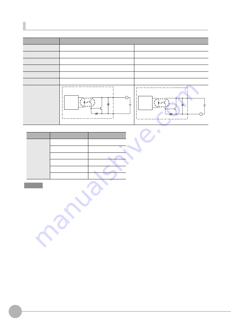
Output circuit
*1 Below is a table giving the COM_OUT (output common) and output signal connection correspondence.
• Connect a load that matches the output specifications. Short-circuit can cause sensor breakdown.
• Keep the load current less than or equal to the specification value. Exceeding the specification value could cause
damage to the output circuit.
Item
Specifications
Model
ZW-CE10T
ZW-CE15T
Output type
NPN
PNP
Output voltage
DC21.6 to 30 V
DC21.6 to 30 V
Load current
50 mA max.
50 mA max.
ON residual voltage
1.2 V max.
1.2 V max.
ON leakage current
0.1 mA max.
0.1 mA max.
Internal circuit diagram
*1
Terminal name
COM_OUT1
COM_OUT2
Output terminal
name
HIGH1
BANK_OUT1
PASS1
BANK_OUT2
LOW1
BANK_OUT3
ALARM
BUSY1
ENABLE1
L
COM_OUT1/2
+
Internal
circuit
Output
terminals
Load
L
+
COM_OUT1/2
Internal
circuit
Output
terminals
Load
Important
Summary of Contents for ZW-C1*AT
Page 17: ...ZW User s Manual 1 15 ...
Page 54: ...Installing the Sysmac Studio 52 ZW User s Manual MEMO ...
Page 74: ...Operating with Sensor Controller 72 ZW User s Manual MEMO ...
Page 120: ...Setting the System 118 ZW User s Manual MEMO ...
Page 138: ...Controll input signal with PC tool 136 ZW User s Manual MEMO ...
Page 262: ...No protocol Connection 260 ZW User s Manual MEMO ...
Page 271: ...8 Troubleshooting Troubleshooting 8 1 Error Messages 270 8 2 Troubleshooting 284 ...
Page 358: ...Connecting by No protocol Communications 356 ZW User s Manual MEMO ...
Page 449: ......


