Installation Instructions EC 2-25 Lift
(Subject to technical alterations! - Status 09/2018)
This is a translation. The German original shall prevail.
Page 31 of 50
•
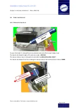
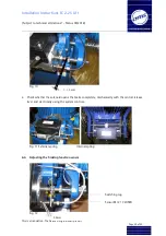
The switching lug must be fitted onto the thread of the brake magnet tappet.
•
The sensor must be installed in the front drill hole with an air clearance of 3,0mm be-
tween the sensor and brake solenoid. The sensors must be adjusted while the brakes are
closed.
Inductive Brake Function Sensor Information
:
Calculated switch clearance: 4,5mm
Standard Function – The electrical circuit is closed when the brake is open
6.7
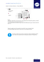
Adjusting the break lining wear control
Fig. 13
•
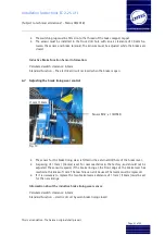
The sensor for the brake lining wear is fitted in the external drill hole of the brake lever.
•
A spacing of 11mm / (14mm) is set for new machines in the factory, and should not be
adjusted. The sensor respond, if the brake lining at the front edge of the brake lever has
reached a thickness of 1mm. The machine can still be used. The levers must be replaced.
•
If it is necessary to replace the two brake levers a distance of 11mm / (14mm) must be set
for the new linings.
Information about the inductive brake lining wear sensor
:
Calculated switch clearance: 4,5mm
Standard Function – electric circuit by worn brake lining closed
11mm / 14mm
Sensor M12 x 1 CLOSER
Summary of Contents for Hypodrive EC 2-25 Lift
Page 2: ......

