Page 31
301 Fulling Mill Road, Suite G ©Copyright 2004 by OnQ Technologies, Inc All Rights Reserved.
Middletown, PA 17057
www.onqhome.com
(800)-321-2343
Innovations in Home Living.
Power Receptacle – Five volt DC power is extracted from the POE Extractor Module in the WAP Assembly
(the 5VDC is derived from the 48VDC fed to the WAP Assembly over the single CAT5e from the POE
Inserter Module in the Enclosure).
LAN Port – Ethernet data is extracted from the POE Extractor Module in the WAP Assembly. The LAN port
supports either 10BASE-T or 100BASE-T transmission speeds as well as straight-through and crossover
Ethernet cables (the Ethernet data is derived from the single CAT5e fed to the WAP Assembly from the POE
Inserter Module in the Enclosure).
Reset Button - A dual-function button. A brief button press resets the WAP unit, while a longer button press
resets the WAP unit to the default login settings. If the WAP is experiencing trouble connecting to the Internet,
briefly press and release the Reset button to reset the WAP. The WAP will retain its configuration information
during this reset operation. To reset the unit to the factory defaults, while the unit is powered, press and hold
the Reset button for more than 10 seconds. This clears the WAP’s user settings, including User ID, Password,
IP Address, and Subnet Mask.
NOTE: Refer to the
Section IV
Initial Configuration Steps
for re-configuring the WAP.
Antenna Connection – Cable connects to the On-Q WAP antenna used for wireless connections.
NOTE: When initially removed from the box, a stub antenna will be connected to this connector. For better
coverage, it should be removed and replaced by the On-Q WAP antenna cable
.
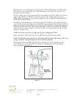
After connections have been verified, or the unit has been reset, insure the CAT5e cable from the POE
Inserter Module is connected, and push the unit through the mounting ring until the Mounting Ring
Clasps snap into place (see
Figure 25
).
Figure 25


