INSTRUCTION/INSTALLATION SHEET
HMS EZ-SCENE ALC LIGHTING INTERFACE
IS-0311 REV. A
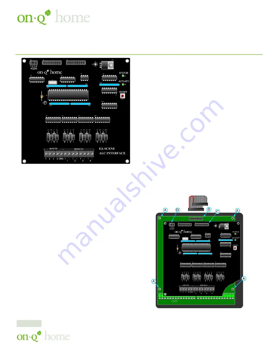
Figure 1. HMS EZ-Scene ALC Lighting Interface
1. Introduction
The part no. 364806 HMS EZ-Scene ALC Lighting Interface
enables any On-Q HMS Controller or HAI OMNI controller to
control On-Q’s Advanced Lighting Controls. Additionally, the
expansion module provides local lighting scene programming
capability. EZ-Scene programming allows ALC 4-Button Scene
Switches and RF Remote Controls to learn the lighting level
settings of ALC Dimmers, Relay Switches and Non-Dimming
controls independent of the HMS Controller.
The part no. 364806-01 1-Branch HMS EZ-Scene ALC
Lighting Interface provides control of up to 31 ALC controls.
The part no. 364806-02 4-Branch HMS EZ-Scene ALC
Lighting Interface provides control of up to 124 ALC controls.
Both expansion module part nos. support a total of 64 EZ-Scene
local lighting scene programs.
The On-Q HMS Model 800 controller provides direct control
of up to 16 ALC controls on branch no. 1. The HMS Model
950 controller provides direct control of 62 ALC controls on
branch nos. 1 and 2. The HMS Model 1100 controller provides
direct control of up to 248 ALC switches using up to two part
no. 364806-02 EZ-Scene ALC Lighting Interface modules.
2. Installation
Note: If other expansion modules are connected to the HMS
controller, the EZ-Scene ALC Lighting Interface must be
installed first, that is directly above the HMS controller.
1. Remove 4 6/32 x 1/4 Phillips screws indicated as "A" in
Figure 2. Replace the screws with the 4 supplied 6/32 x 1/2
male/female Hex Standoffs. Retain screws for future step.
2. Connect supplied cable to 20 pin connector on controller
indicated as "B" in Figure 2.
3. Align the interface PCB with the hex standoffs and secure
with the 4 screws removed in step 1.
4. Connect opposite end of supplied cable to the 20 pin
connector on the interface PCB indicated as "C" in Figure 2.
5. Ensure that the address jumper indicated as "D" in Figure 2,
is set to a unique address. Factory setting is address no. 2.
Note: This example is for the HMS 800. For Models 950 and
1100 mounting is to the right side of the controller, the same
procedure should be followed.
Figure 2. HMS EZ-Scene ALC Lighting Interface Mounting
Page 1 of 4
301 Fulling Mill Road, Suite G ©Copyright 2005 by OnQ Technologies, Inc All Rights Reserved.
Middletown, PA 17057
www.onqhome.com
(800)-321-2343
Innovations in Home Living.


