background image

NOTE:

Some parts are listed and shown for illustration purposes only, and are not

available individually as replacement parts.

SKU 92497         For technical questions, please call 1-800-444-3353          PAGE 12

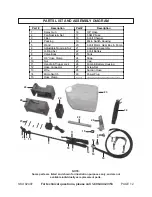
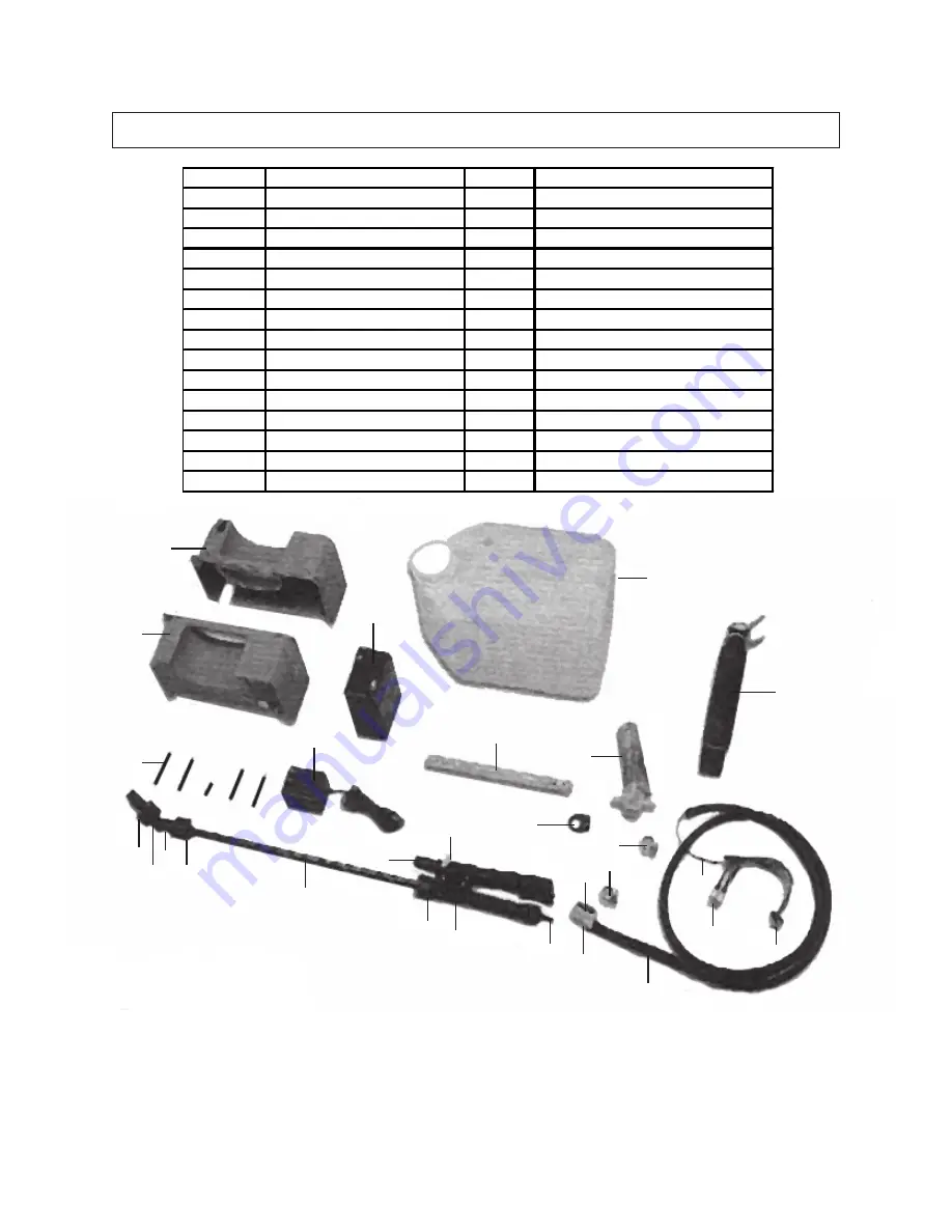
PARTS LIST AND ASSEMBLY DIAGRAM

26

26

23

22

24

28

27

18

20

16

9
9

15

5

11

2

4

3

17

14

19

29

6

1

13

12

Part #

Description

Part #

Description

1

Spray Gun

16

3/8” Hose

2

Fan Nozzle & Nut

17

5 AMP Fuse

3

Filter

18

6 Volt Charger

4

Packing

19

Micro Switch Housing

5

Wand

20

6 Volt Motor, Gear Box, & Pump

6

Adjustable Nozzle & Nut

21

Liquid End Assembly

7

O-Ring Set

22

6 Volt Battery

8

Valve Body

23

Tank

9

3/8” Hose Clamp

24

Strap

10

Nut

25

Cap

11

Handle & Trigger Lock

26

Pump & Battery Housing

12

Hose Connector

27

Screw Set

13

Wire

28

Suction Hose

14

Micro Switch

29

Power Plug

15

Hose Clamp

--------

----------------------------------------

10

10

Summary of Contents for 92497

Page 1: ...UNDERSTAND ALL WARNINGS AND INSTRUCTIONS BEFORE USE Copyright 2004 by Harbor Freight Tools All rights reserved No portion of this manual or any artwork contained herein may be reproduced in any shape...

Page 2: ...92497 For technical questions please call 1 800 444 3353 PAGE 2 UNPACKING When unpacking check to make sure all the parts shown on the Parts Lists on page 12 are included If any parts are missing or...

Page 3: ...and balance at all times Proper footing and balance enables better control of the power tool in unexpected situations 5 Use safety equipment Always wear ANSI approved safety glasses under a full face...

Page 4: ...t may affect the tool s operation If damaged have the tool serviced before using Many accidents are caused by poorly main tained tools 7 Use only accessories that are recommended by the manufacturer f...

Page 5: ...or at other live electrical equipment 7 When using the Sprayer always maintain a firm grip on the Spray Gun 1 with both hands Squeezing the Handle 11 of the Spray Gun causes a kick back force 8 Do not...

Page 6: ...permanently damaged Never over discharge a Battery by using the tool while tool performance is decreasing Never attempt to discharge a tool s Battery by continuing to squeeze the tool Handle 11 When...

Page 7: ...the Motor will automatically shut off See Figure A 2 NOTE The Sprayer will not pressurize if any part of the tool is not completely assembled and free of air and water leaks 3 The Sprayer is equipped...

Page 8: ...cur See Figure B To Charge The Battery 4 To charge the Battery 22 make sure the Trigger Lock 11 is engaged in its OFF position Insert the Charger Plug of the Charger 18 into the Charging Socket locate...

Page 9: ...discussed in Step 1 NOTE The Adjustable Nozzle Nut can provide a higher impact spray and can possibly damage surfaces Use caution as a concentrated pattern can cause damage to the surface being spray...

Page 10: ...off the tool Empty the Tank 23 of its contents making sure to replace the Cap 25 on the Tank Disengage the Trigger Lock and squeeze the Handle 11 to release any remaining pressure in the system Then...

Page 11: ...the Sprayer of liquid Frost will dam age the Sprayer if the unit contains liquid Store the Sprayer indoors in a dry frost free room Minerals in the water can harden inside the workings Flush the unit...

Page 12: ...1 13 12 Part Description Part Description 1 Spray Gun 16 3 8 Hose 2 Fan Nozzle Nut 17 5 AMP Fuse 3 Filter 18 6 Volt Charger 4 Packing 19 Micro Switch Housing 5 Wand 20 6 Volt Motor Gear Box Pump 6 Ad...

Reviews: