background image

SKU 94593

        For technical questions, please call 1-800-444-3353

Page 5

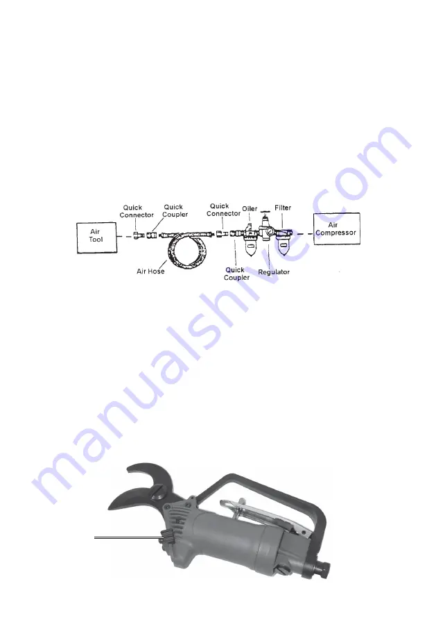
Oiler and Filter Connection

Dirt, water, and the lack of pneumatic tool oil are major causes for tool wear. Install
an optional oiler-filter, as illustrated below for better performance.

1.

Connect the air tool, air hoses, filter, and oiler to the Compressor Air Outlet

as illustrated below.

The filter and oiler (not supplied) are recommended but not mandatory for

operation. Also, for ease of air supply transport, a portable, rechargeable air
supply would make it easier to maneuver the garden for trimming.

If the filter and oiler are not used, connect the air hose directly to the 1/4 inch,

18 NPT connector located at the Air Inlet (12) fitting. Also, a few drops of
pneumatic tool oil must be added through the Air Inlet (12) before each use.

Note: Use pipe thread seal or Teflon tape on all threaded connections.

Operation

1.

Place the air supply, sufficient length of air hose, and Pneumatic Shears near

the tree or shrubs to be trimmed.

2.

Turn the air pressure on at the air supply tank or compressor.

3.

Brace yourself on the ground or ladder, then grasp the Pneumatic Shears by

the handle.

4.

Place the open blades over the branch to be cut.

5.

Pull the Blade Safety Latch (38) down to unlock the blades.

Blade Safety
Latch (38)

Summary of Contents for 94593

Page 1: ...bor Freight Tools All rights reserved No portion of this manual or any artwork contained herein may be reproduced in any shape or form without the express written consent of Harbor Freight Tools For technical questions and replacement parts please call 1 800 444 3353 94593 Due to continuing improvements actual product may differ slightly from the product described herein ...

Page 2: ...area Do not let them handle machines tools or extension cords 4 Store idle equipment When not in use tools must be stored in a dry location to inhibit rust Always lock up tools and keep out of reach of children 5 Use the right tool for the job Do not attempt to force a small tool or attachment to do the work of a larger industrial tool There are certain applications for which this tool was designe...

Page 3: ...should be carefully checked to determine that it will operate properly and perform its intended function Check for alignment and binding of moving parts any broken parts or mounting fixtures and any other condition that may affect proper operation Any part that is damaged should be properly repaired or replaced by a qualified technician Do not use the tool if any switch does not turn On and Off pr...

Page 4: ...cted to release any residual air in the chamber 4 Wear work gloves to protect your hands Warning The warnings cautions and instructions discussed in this instruction manual cannot cover all possible conditions and situations that may occur It must be understood by the operator that common sense and caution are factors which cannot be built into this product but must be supplied by the operator Unp...

Page 5: ...neuver the garden for trimming If the filter and oiler are not used connect the air hose directly to the 1 4 inch 18 NPT connector located at the Air Inlet 12 fitting Also a few drops of pneumatic tool oil must be added through the Air Inlet 12 before each use Note Use pipe thread seal or Teflon tape on all threaded connections Operation 1 Place the air supply sufficient length of air hose and Pne...

Page 6: ... the Air Compressor Operator s Manual Manual Tool Lubrication 1 Disconnect the Pneumatic Shears from the air supply and turn it so the Air Inlet 12 fitting is facing upward 2 Hold the Trigger Lever 22 in and place one teaspoon of pneumatic tool oil into the air inlet use SAE 10 weight oil if air tool oil is not available Holding the Trigger Lever in helps circulate the oil in the air motor 3 Conne...

Page 7: ...2 Trigger Lever 1 44 Blade Set 27 28 29 1 NOTE Some parts are listed and shown for illustration purposes only and are not available individually as replacement parts PLEASE READ THE FOLLOWING CAREFULLY THE MANUFACTURER AND OR DISTRIBUTOR HAS PROVIDED THE PARTS DIAGRAM IN THIS MANUAL AS A REFERENCE TOOL ONLY NEITHER THE MANUFACTURER NOR DISTRIBUTOR MAKES ANY REPRESENTATION OR WARRANTY OF ANY KIND T...

Page 8: ...SKU 94593 For technical questions please call 1 800 444 3353 Page 8 Assembly Drawing ...

Reviews: