background image

One Stop Systems


ExpressBox 3T-V3   | 25 


3     Verify Installation 

3.1  Hardware 

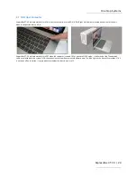
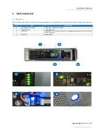
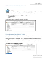
Check the status of the LEDs on the Interface cards and backplane to verify good connection or link between your host computer and expansion 
unit. 

NO 

LED 

DESCRIPTION 

Thunderbolt 3 card LEDs 

5 solid green LEDS are illuminated 

Backplane LEDs 

2 solid green LEDs 

Slot LED 5 

1 Solid Blue LED.  If not all three SLOTS are populated with cards, only LED5 for SLOT1 
will be illuminated. 

Front LED 

Solid Blue LED. 


Summary of Contents for EB3T-V3

Page 1: ...ExpressBox 3T V3 Model EB3T V3 www onestopsystems com User Manual ...

Page 2: ...3 1 6 2 J1 connector 14 1 7 Backplane 14 1 7 1 PCIe card Slots 15 1 7 2 J6 15 1 7 3 SW1 switch module 15 1 7 4 SW2 switch 15 1 7 5 JP5 16 1 7 6 J2 J3 and J4 16 1 7 7 J10 16 1 7 8 J11 connector 17 1 8 Backplane LEDs 17 1 8 1 LED1 17 1 8 2 LED2 18 1 8 3 LED3 18 1 9 SLOT LEDS 18 1 9 1 LED5 for SLOT1 18 1 9 2 LED6 for SLOT2 18 1 9 3 LED7 for SLOT3 18 1 9 4 LED8 for SLOT4 19 1 10 Pre Installation Infor...

Page 3: ...10 10 or newer 30 4 3 Thunderbolt Aware Driver is required for PCIe cards 30 4 4 PCIe Card and Slot assignment 31 4 5 How to Check EB3T Device on Windows 10 32 4 6 How to check PCIe card on Windows10 33 5 Important Technical Information 34 5 1 Shipping Transporting the unit 34 5 2 Fan Specifications 34 5 3 Fan Speed and Noise Adjustment 35 5 3 1 Tools 35 5 3 2 Steps to adjust the fan speed 35 5 4 ...

Page 4: ...vice 56 6 2 2 How to Check PCIe card device 58 7 GPU Installation 59 7 1 Step 1 Set Up EB3T V3 59 7 1 1 Install Thunderbolt Software and reboot 60 7 2 Step 2 Install GPU 63 7 3 Step 3 Install GPU Software 63 7 4 Quadro GPU Driver Installation Guide 63 7 5 How to verify Thunderbolt device and eGPU card 64 8 Troubleshooting 68 9 How to Get More Help 72 9 1 Contacting Technical Support 72 9 2 Returni...

Page 5: ...p to help you CAUTION Used to indicate and prevent the following procedure or step from causing damage to the equipment WARNING Used to indicate and prevent the following step from causing injury DANGER or STOP Used to indicate and prevent the following step from causing serious injury or significant data loss Disclaimer We have attempted to identify most situations that may pose a danger warning ...

Page 6: ...y cause your installation to produce emissions that could interfere with other electronic equipment in the area of your system When Working Inside a Computer 1 Before taking covers off a computer perform the following steps 2 Turn off the computer and any peripheral devices 3 Disconnect the computer and peripheral power cords from their AC outlets or inlets in order to prevent electric shock or sy...

Page 7: ...hich can include wrist straps and smocks when servicing equipment You can also take the following steps to prevent damage from electrostatic discharge ESD When unpacking a static sensitive component from its shipping carton do not remove the component s anti static packaging material until you are ready to install the component in a computer Just before unwrapping the anti static packaging be sure...

Page 8: ...rbolt 3 cable provides four times the data and twice the video bandwidth while also supplying power Gives the user the power to use for 4K video single cable docks with charging and built in 10 G networking PCI Express Features Supports three full length cards This chassis includes a PCI Express Gen 3 switch with 48 lanes Three slots slot2 slot3 and slot4 are all x8 lanes Gen3 Slot 1 is the upstre...

Page 9: ...T V3 9 No Slot 1 PCIe SLOT1 2 PCIe SLOT2 3 PCIe SLOT3 4 PCIe SLOT4 1 1 Core of EB3T Thunderbolt 3 The PCIe slot connector is x16 but the Thunderbolt3 card is x4 Therefore upstream port will operate at x4 speed Figure 1 2 Figure 1 4 ...

Page 10: ...nated closed type as there is a heatsink at the end of the slot NO 3 a x16 card cannot be installed in the slot 1 2 Parts List Number Qty Item 1 1 ExpressBox 3T V3 Three Slot PCIe Expansion Chassis 2 1 Fan Blower 3 1 Carry Bag 4 1 U S Standard 115V Power Cord ...

Page 11: ...oise Level 10 db Power Supply Options 300 Watt 100 240 VAC 50 60 Hz Power Input Two 8 pin auxiliary power tabs One 4 pin auxiliary Molex power connector Environmental Ambient Temperature 0 to 50 C Storage Temperature 20 to 60 C Relative Humidity 5 to 85 non condensing MTBF 50 000 Regulatory Compliance FCC Class A Verified CE RoHS Compliant Thunderbolt 3 Supported Operating Systems MacOS 10 10 or h...

Page 12: ...One Stop Systems ExpressBox 3T V3 12 1 5 Parts of EB3T ...

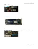
Page 13: ...d indicator LEDs LED1 5VSB LED2 3V3 LED3 5V0_ATX LED4 3V3_LC LED5 0V9_SVR When LED1 and LED2 are illuminated it indicates Thunderbolt 3 enclosure is at standby mode When LED1 through LED5 are illuminated it indicates Thunderbolt 3 enclosure turns on or the unit is operational ...

Page 14: ... The 3 pin cable from PSU connects to J1 and provides 5VSB power to Thunderbolt 3 card The EB3T unit will not turn ON when the 3 wire power cable is disconnected from the J1 connector J1 connector spec name JST 3 pin 2 5 mm pitch XH connector 1 7 Backplane ...

Page 15: ... 7 3 SW1 switch module SW1 1 ON default The enclosure is powered on off by host computer The TB3 enclosure is set at ON by default OFF The OFF setting is for external PCIe interface products For the Thunderbolt 3 enclosure there is no function when it is set at OFF position SW1 2 ON NP951AG3 backplane onboard fan is set for full speed at 6000 RPM OFF default NP951AG3 backplane onboard fan is set f...

Page 16: ...y this print as the correct description JP5 Compatibility Enable in the next release of backplane 1 7 6 J2 J3 and J4 J2 connector is used for other PCIe expansion products for the purpose of powering on off by host J3 connector is used for other product it sends the power good signal to controller board to activate the solenoid actuator within the enclosure J4 connector is used for other product i...

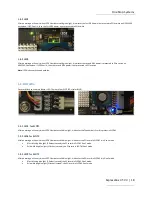
Page 17: ...provides electric power to NP951AG3 backplane s onboard fan 1 8 Backplane LEDs 1 8 1 LED1 When LED1 illuminates solid green light it indicates the 3 3V aux power is presented to NP951AG3 backplane If LED1 not lit then 3 3V aux power is not presented to backplane ...

Page 18: ... indicator LED There are four SLOT LEDs color BLUE 1 9 1 LED5 for SLOT1 After powering on the unit when LED5 illuminates solid blue light it indicates the Thunderbolt 3 card is present in SLOT 1 1 9 2 LED6 for SLOT2 After powering on the unit when LED6 illuminates solid blue light it indicates the PCIe card in SLOT 2 is in Gen3 mode If fast blinking blue light 2 flashes second the PCIe card in SLO...

Page 19: ...es second the PCIe card in SLOT 4 Gen1 mode 1 10 Pre Installation Information Before using the expansion chassis you should perform the following steps Inventory the shipping carton contents for all of the required parts Gather all of the necessary tools required for installation Read this manual 1 11 Tools Required for Installation To complete the installation of the One Stop Systems product you ...

Page 20: ...rds see notes below 3 Attach Power Cord 4 Connect Thunderbolt cable 5 Start Host computer 6 Hardware Check 7 Verify Installation via Operating System When installing 3rd Party PCIe card start with one card first just to see if there are any software and hardware issues or incompatibility problems that may occur This way you can troubleshoot the problem more easily and efficiently If everything wor...

Page 21: ...er Slot 4 accepts x1 x4 x8 and x16 PCIe cards or the provided Fan Blower Slot 3 accepts x1 x4 or x8 PCIe cards Slot 2 accepts all types of PCIe cards x1 x4 x8 or x16 next to Thunderbolt interface card Slot 1 designated slot for Thunderbolt interface card Make sure that all cards are fully seated in their connectors To keep the cards in place secure them in the enclosure with their retaining screws...

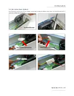
Page 22: ...3T V3 22 2 4 1 Add in System Blower Optional If the PCIe cards run hot or are over 20 watts of power we recommend installing the additional system blower in the Slot4 of ExpressBox 3T V3 Use caution if loading three cards at once ...

Page 23: ...hunderbolt logo is visible on top of the connector this indicates that you are using a certified Thunderbolt cable Attach Thunderbolt cable into either top or bottom port on the ExpressBox 3T V3 Plug in the other end of the Thunderbolt cable to the Thunderbolt port on the computer Plug in Display Monitor DVI HDMI or Display If no display will be used you can daisy chain other Thunderbolt devices ...

Page 24: ... unit when the expansion chassis is ON ExpressBox 3T V3 will automatically turn OFF when the computer is turned OFF or goes into SLEEP mode If either end of the Thunderbolt cable is removed while the system is ON the expansion chassis will automatically power down The Blue light on the front of ExpressBox 3T V3 is not an on off push button it simply indicates whether the chassis is on or off ...

Page 25: ...to verify good connection or link between your host computer and expansion unit NO LED DESCRIPTION 1 Thunderbolt 3 card LEDs 5 solid green LEDS are illuminated 2 Backplane LEDs 2 solid green LEDs 3 Slot LED 5 1 Solid Blue LED If not all three SLOTS are populated with cards only LED5 for SLOT1 will be illuminated 4 Front LED Solid Blue LED ...

Page 26: ...en the Thunderbolt 3 Interface card is operational and it indicates that the Thunderbolt3 unit is ON 3 2 2 LED status Standby mode LED1 and LED2 are illuminated it indicates the expansion unit is on standby mode waiting to be powered up See picture below 3 3 Backplane LEDs Two Solid Green LEDs illuminated are visible on the backplane and 1 Solid Blue LED slot 1 LED5 ...

Page 27: ...when LED2 illuminates solid green light it indicates the first 0 9V power is presented to PCIe switch on NP951AG3 backplane If LED2 not lit then the first 0 9V power is not presented to PCIe switch 3 3 3 LED5 for SLOT1 After powering on the unit when LED5 illuminates solid blue light it indicates the Thunderbolt 3 card is present in SLOT 1 IMPORTANT If the above three LEDs are not coming ON you ma...

Page 28: ...r on Apple Mac Operating System and Windows OS 7 and 10 4 1 How to check EB3T device on Mac OS 10 10 or newer After setting up the EB3T hardware the next step is to verify the installation of on Mac System Report Click Thunderbolt select and click Thunderbolt Bus 0 expand or collapse the arrow ...

Page 29: ...olt3 Series select it and you should see the following info Vendor Name as Magma Device Name as Tbolt3 Series Vendor ID 0x58 Device ID 0x211c If you select USB you should see Thunderbolt3 v3 This is the One Stop Systems expansion unit see screenshot below ...

Page 30: ...underbolt Aware Driver is required for PCIe cards For Mac OS a Thunderbolt Aware Compatible driver is required because it allows PCIe cards to be detected Ensure you have a Thunderbolt Aware or Thunderbolt Compatible driver from the PCIe card manufacturer otherwise the PCIe card will not function properly If the driver is installed make sure it supports Thunderbolt If the driver does not support T...

Page 31: ...ndor or manufacturer If you would like to determine whether the 3rd party PCIe card has a Thunderbolt Compatible driver or not you must contact the vendor or manufacturer of the PCIe card 4 4 PCIe Card and Slot assignment Thunderbolt 196 0 0 is assigned to PCIe card present in SLOT 2 Thunderbolt 195 0 0 is assigned to PCIe card present in SLOT 3 Thunderbolt 198 0 0 is assigned to PCIe card present...

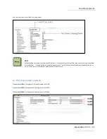
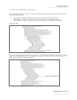
Page 32: ...d expand PCI Express Root Port 5 You should see one instance of PCI Express Upstream Switch Port Select and expand PCI Express Upstream Switch Port You should see one instance of Thunderbolt Controller 1575 See screenshot below Within the tree select and expand PCI Express Downstream Switch Port Select and expand PCI Express Upstream Switch Port Select and expand PCI Express Downstream Switch Port...

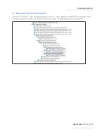
Page 33: ...n Windows10 When you see this symbol next to PCI Express Downstream Switch Port it means expandable or collapsible Select and expand all three PCI Express Downstream Switch Ports and all three PCIe card devices installed in the EB3T will show up see screenshot below ...

Page 34: ...cards should be removed or not to be installed prior to shipping to avoid or prevent possible damage 5 2 Fan Specifications Airflow 22 7 37 0 CFM Static Pressure 1 3 4 4 mm H2O Blade Housing Plastic Material UL 94V 0 P B T Lead Wire UL1007 24 AWG Weight 85 0 g Bearing Rate Voltage Operating Voltage Range Speed Max Airflow Max Static Pressure Current Power Consumption Life at 40 C L10 P Q Curve Noi...

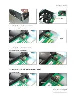
Page 35: ...e chassis and you will see a small board as shown below The Factory Default is setting 2 medium The slowest speed is setting 4 and the fastest speed is setting F F fastest 1 fast 2 medium default 3 slow 4 slowest The factory Default setting is 2 medium The slowest speed setting is 4 and the fastest speed setting is F 5 3 1 Tools 5 3 2 Steps to adjust the fan speed Pull the fan out from the unit Se...

Page 36: ...etting the Fan to maximum speed mode Move the jumper to pin F see photo below 5 3 4 Setting the Fan to slowest speed mode Move the jumper to PIN 4 see photo below 5 3 5 Setting the Fan to medium speed mode default setting Move the jumper to PIN 2 ...

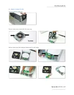
Page 37: ...ms ExpressBox 3T V3 37 5 4 How to replace the fan Pull the front fan out from the unit Remove the two screws to dismount fan from the housing Remove the two screws from circuit board and separate it from the housing ...

Page 38: ...al steps in reverse order Make sure the fan logo is facing down towards the housing Correct orientation of the fan see photos below 5 6 Installation of x16 PCIe card Use SLOT2 and SLOT4 when installing a x16 card The 2ND and 4TH PCIe slots have an open ended slot on the far end of the connector See pictures below Installing x16 card in SLOT 2 ...

Page 39: ...Installation Prior to installing the HDx cards you need a PCIe AUX power cable Avid supplies the required auxiliary power cable If you do not have the AUX power adapter cable you need to contact AVID There are two types of HDx auxiliary power cables provided by AVID One is for Mac installation and the other is for PC installation see photos below You can use either the PC or Mac HDx Aux power Note...

Page 40: ...ct the HDx power cable 5 7 2 Using HDx power cable for PC Pull out the Aux power cable from inside the EB3T and connect the HDx power cable Install the HDx card Use the slot1 for the 1st HDx card Align the HDX card above the card guide slot and push it down slowly until firmly seated into the slot ...

Page 41: ...l the next HDX card use the 2nd slot Secure both HDx cards Attached the HDx power cable to HDX cards Connect the HDx TDM cable to the cards For Pro Tools software installation and configuration you need to contact Avid Digidesign for assistance ...

Page 42: ...9 at full load Inrush current regulation The power supply must meet inrush requirements for any rated AC voltage during turn on at any phase Of AC voltage during a single cycle AC dropout condition during repetitive ON OFF cycling of AC and over the specified temperature range Top The peak inrush current shall be less than the ratings of its critical components including input fuse bulk rectifiers...

Page 43: ...ll outputs The supply shall provide latch mode over voltage protection as defined in Table Parameter Minimum Nominal Maximum Unit 12 VDC 13 4 15 0 13 Volts 5 VDC 5 74 6 3 14 Volts 3 3 VDC 3 76 4 2 20 Volts Short circuit An output short circuit is defined as any output impedance of less than 0 1 ohms The power supply shall shut down and latch off for shorting the 3 3 VDC 5 VDC or 12 VDC rails to re...

Page 44: ... FREQUENCY MAGNETIC FIELD IEC 61000 4 8 2009 VOLTAGE DIPS IEC 61000 4 11 2004 RADIATED SUSCEPTIBILTY IEC 61000 4 3 2006 A1 2007 A2 2010 CONDUCTED SUSCEPTIBILTY IEC 61000 4 6 2008 VOLTAGE FLUCTATION EN 61000 3 3 2008 EN61000 3 2 2006 A2 2009 harmonic current emissions If applicable to sales in Europe the power supply shall meet the requirements of EN 61000 3 2 Class D and the Guidelines for the Sup...

Page 45: ...continuous operation at 25 C 75 of full load and 120V AC input The MTBF of the power supply shall be calculated in accordance with MIL HDBK 217F The DC FAN is not included MECHANICAL REQUIREMENTS Physical dimension B type L150 W81 5 H40 5 Connectors Connectors INTEL approved equivalent ...

Page 46: ...Red Black COM 17 7 COM Black White NC 18 8 PG Grey 22 AWG Red 5VDC 19 9 5VSB Purple 20 AWG Red 5VDC 20 10 12VDC Yellow Red 22 AWG 5V sense Red 5VDC B3 B1 12V1 Yellow Black COM B4 B2 3 3V Orange P2 Optional Connector Molex 39 01 2060 or equivalent 18 AWG Wire Signal Pin Pin Signal 18AWGwire Black GND 1 3 Yellow 12V Black GND 2 4 Yellow 12V P3 P4 Molex 8981 04P or equivalent 18 AWG Wire Signal Pin Y...

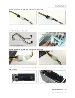
Page 47: ...iary Power Cables The EB3T V3 internal power supply comes with one Molex 4 pin and two PCIe 6 2 pin connectors You can find the the three auxiliary power cables inside the EB3T V3 unit If you need an extra 4pin Molex connector you can use a Y Splitter molex connector You can buy the Y Splitter from any online eletrectronic stores Search for 4 Pin Molex Y Splitter online ...

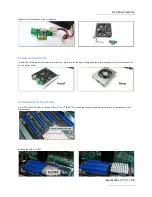
Page 48: ...r Thunderbolt port on ExpressBox 3T V3 Make sure your display is plugged in and the appropriate adapter is connected 5 11 How to Remove Thunderbolt3 card If you need to replace the Thunderbolt3 card follow the steps below Remove the screw on top of the mounting bracket Disconnect the 3 pin wire power cable from the Interface card as shown from pictures below Gently pull the Thunderbolt Interface c...

Page 49: ...ower Supply Disconnect the 3 wire power cable from the Thunderbolt3 card J1 connector Unplug the 24 pin ATX power cable from the backplane Remove the screws on both side panels there are two side panels Remove the four rubber feet by removing the four screws ...

Page 50: ...nnect the 4 pin cable from the power supply see picture below Remove the following screws two screws under the unit and one on the back of the unit Pull the power supply out from the unit To install the power supply follow the power supply removal steps in reverse order ...

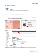
Page 51: ...derbolt Software If you are using Intel NUC computer you have to download the Thunderbolt 3 software and firmware from Intel Here is the link to the previous Thunderbolt software by Intel https downloadcenter intel com download 23742 Thunderbolt Intel Thunderbolt driver When downloading is completed do the following Select and run Thunderbolt Software Welcome to Thunderbolt TM Software Setup Wizar...

Page 52: ...One Stop Systems ExpressBox 3T V3 52 ...

Page 53: ...One Stop Systems ExpressBox 3T V3 53 ...

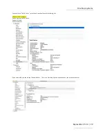
Page 54: ... Root Port look for a sub device PCI Express Upstream Switch Port select and expand it An instance of another sub device PCI Express Downstream Switch Port is present select and expand it An instance of Thunderbolt TM Controler 156a is detected This is the Thunderbolt controller card Select and expand another PCI Express Downstream Switch Port This is the EB3T PCIe slot Below the PCI Express Downs...

Page 55: ...One Stop Systems ExpressBox 3T V3 55 ...

Page 56: ...nnecting the EB3T V3 unit make sure that the Thunderbolt feature is enabled in the BIOS Connect the EB3T V3 to laptop Turn ON the Laptop EB3T will power up instantly 6 2 1 How to Check EB3T device EB3T V3 Thunderbolt expansion unit requires no special drivers software on Linux operating systems For reference vendor ID list for Thunderbolt3 Bridge 1575 DSL6340 Thunderbolt 3 NHI Alpine Ridge 2C 2015...

Page 57: ...command The Vendor ID 1566 was for Thunderbolt2 Replace the 1566 with the current Thunderbolt3 Vendor ID with the following 1575 1576 1577 or 1578 You need to check for PCI Bridges on the terminal window type lspci vvv grep 156d command You can use lspci vvv grep 156 command It will display all PCI bridges and Intel devices ...

Page 58: ...type lspci vtt command You can view the detailed device information of a specific PCIe card device you would need the slot number in the domain bus slot func format you can query for a particular device as shown below For example looking at the lspci vtt output see picture above we will look up the ATTO Technology Open the terminal window and type lspci s 0b 00 0 vb see output below ...

Page 59: ...nstalled or not The computer s manufacturer provides the Thunderbolt Software A Thunderbolt Software is required prior to connecting and using the Magma Thunderbolt EB3T expansion unit or any external Thunderbolt devices with thunderbolt equipped laptop PC computers Without the Thunderbolt Software your Laptop s OS will not detect the Magma Thunderbolt expansion unit Check your laptop first see if...

Page 60: ...thunderbolt unit first before connecting the Thunderbolt cable See Picture 5 If this is the first time you are connecting a new Thunderbolt device you will see a pop up message New Thunderbolt device have been attached click OK See Picture 6 Do you want this APP to make changes click OK See Picture 7 Pop up message Approve Thunderbolt Devices Attached select from the drop down list always connect ...

Page 61: ...One Stop Systems ExpressBox 3T V3 61 PICTURE 3 PICTURE 4 PICTURE 5 ...

Page 62: ...One Stop Systems ExpressBox 3T V3 62 PICTURE 6 PICTURE 7 PICTURE 8 PICTURE 9 ...

Page 63: ...ting the Thunderbolt device 13 After the host computer has started UP reconnect the Thunderbolt cable to EB3T V3 14 Your external Thunderbolt3 device and eGPU should be detected 7 4 Quadro GPU Driver Installation Guide A Quadro eGPU solution consist of a PCIE based Quadro graphics card hosted in an external enclosure box connected to a host laptop desktop system through Thunderbolt 3 interface For...

Page 64: ... OS Windows 10 RS2 I O Thunderbolt 3 Port Driver Quadro Driver 384 or newer Recommended host system specifications to run Professional application on Quadro eGPU CPU Intel i5 Xeon E3 or greater Memory RAM 8GB or greater External monitor For optimum performance connect an external monitor to eGPU o Mandatory Monitor must be connected to Quadro eGPU for VR applications to run 7 5 How to verify Thund...

Page 65: ...One Stop Systems ExpressBox 3T V3 65 PICTURE A2 PICTURE A3 PICTURE A4 ...

Page 66: ...One Stop Systems ExpressBox 3T V3 66 PICTURE A5 PICTURE A6 PICTURE A7 ...

Page 67: ...One Stop Systems ExpressBox 3T V3 67 ...

Page 68: ...e 3 Check if the SLOTS LED are illuminated you should see one Solid Blue LED and two or three Blue LEDS blinking 4 If all LEDS are verified working this means the EB3T has powered UP ok and working fine 5 This also indicates that the Thunderbolt cable is working fine 6 Your next step is to try another PCIe card see if this card shows up or not 7 If the card shows up this means that your original P...

Page 69: ...nd connected you should see five solid green LEDs shown illuminated on the Thunderbolt 3 card and a solid blue LED illuminated on the front of the unit Q If ExpressBox 3T V3 does not power up how do I determine whether I have a bad power supply a bad interface card or defective cable A First try another Thunderbolt 3 cable if this fixes the problem it means that you have a faulty cable If the prob...

Page 70: ...witch J5 on the backplane setting it to proper configuration to match the PCIE card specs Compatibility Enable Mode jumper being placed over pin 1 and 2 There may be some PCIe Gen1 cards whose signal doesn t fully comply with PCI Express protocol select this mode to allow non compliant Gen1 card to work with downstream slot no 2 4 within the enclosure Standard Mode jumper being placed over pin 2 a...

Page 71: ...er without any PCIe cards installed Yes In Apple System Profiler Thunderbolt Status Connected ExpressBox 3T In Windows Control Panel Device Manager View by connection You should see these three PCI to PCI bridges Right click on it and select Properties select Hardware Ids from dropdown list you should see PCI Ven_111D ...

Page 72: ...ce Please note that One Stop Systems WILL NOT accept COD packages so be sure to return the product freight and duties paid Ship the well packaged product to the address below Attention RMA ________ One Stop Systems 9918 Via Pasar San Diego CA 92126 USA It is not required though highly recommended that you keep the packaging from the original shipment of your product However if you return a product...

Page 73: ...es Operation is subject to the following two conditions 1 this device may not cause harmful interference and 2 this device must accept any interference received including interference that may cause undesired operation Changes or modifications not expressly approved by the party responsible for compliance could void the user s authority to operate the equipment NOTE The assembler of a personal com...

Page 74: ...Manual P N 09 09989 02 Rev A ...

Reviews: