background image

CDR45I

Power Conditioner 

User Manual

IMPORTANT SAFETY INSTRUCTIONS

SAVE THESE INSTRUCTIONS.

This Manual contains important instructions for the CDR Series Model CDR45I Power Conditioners
which should be followed during their unpacking, installation and maintenance. 

Model Number   CDR45I

Part Number _____________________________________________________

Serial Number____________________________________________________

©2004 ONEAC Corporation  

Summary of Contents for CDR45I Series

Page 1: ...nt instructions for the CDR Series Model CDR45I Power Conditioners which should be followed during their unpacking installation and maintenance Model Number CDR45I Part Number ________________________...

Page 2: ...ax 847 680 5124 ONEAC Europe George Curl Way Southampton Hampshire SO18 2RY United Kingdom Tel 44 0 2380 610311 Fax 44 0 2380 612039 Visit our website at www oneac com 2004 ONEAC Corporation ONEAC and...

Page 3: ...oltage If voltages do not match damage to equipment may result Safety Information The following general safety precautions must be observed during all phases of operation service and repair of this sy...

Page 4: ...result in personal injury Any adjustment maintenance or repair of the opened system under voltage should be avoided as much as possible and when inevitable should be carried out only by a skilled per...

Page 5: ...d cautions to denote hazards WARNING A warning calls attention to a procedure practice or the like which if not correctly performed or adhered to could result in injury or the loss of life Do not proc...

Page 6: ...Safety Information 6 ONEAC CDR45I Series Power Conditioner Installation Guide 913 521 Rev A...

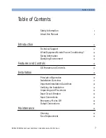
Page 7: ...onditioning 12 Sizing Information 12 Operating Environment 12 Features and Controls 13 I O Features and Controls 13 Installation 15 Principle of Operation 15 Installation Overview 17 Important Install...

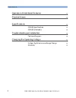
Page 8: ...913 521 Rev A Operation of Additional Features 37 Physical Views 39 Specifications 41 CDR45I Specifications 41 CDR45I Schematics 45 Troubleshooting an Installation 49 Technical Support 49 Changing th...

Page 9: ...24 Figure 6 24 Vac control circuit 28 Figure 7 Position of emergency off fuses and emergency off transformer 29 Figure 8 Position of the output connections 30 Figure 9 Fuse replacement 35 Figure 10 Vi...

Page 10: ...List of Figures 10 ONEAC CDR45I Series Power Conditioner Installation Guide 913 521 Rev...

Page 11: ...l Services North America 800 327 8801 option 3 847 816 6000 option 3 Europe 44 0 2380 610311 email ts oneac com NOTE All calls received before 7 a m or after 7p m Central Standard Time are forwarded t...

Page 12: ...r ONEAC CDR45I Series Power Conditioner lists the model s current rating nominal input and output voltage and serial number The combined steady state RMS current draw of all your equipment must not ex...

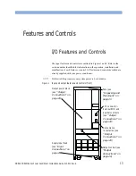
Page 13: ...d controls described are already supplied with your power conditioner NOTE Field retrofitting requires your system power to be shut down Figure 1 Input and output features and controls front Output po...

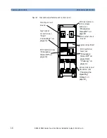
Page 14: ...reaker Input conduit connection see Input Connections on page 23 EMO red mushroom turn to release button see Emergency Mains Off on page 26 Main output circuit breaker Spares compartment 3 phase mains...

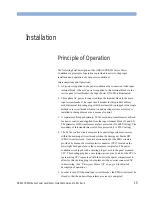
Page 15: ...imary 24 Vac secondary transformer is utilized for power control and supplied from the input terminal block L1 and L2 The primaries of this transformer are fuse protected 2A 600 V rating The secondary...

Page 16: ...applied to the cooling fans and the main output circuit breaker When the main output circuit breaker in turned ON the Output Power ON LED is illuminated and power is available at the output power bloc...

Page 17: ...use in connecting the input wires to the input power block Use a grounding conductor that is equal to or larger than the current carrying conductors Do not connect a neutral wire to the delta input of...

Page 18: ...ired in a DELTA WYE configuration Figure 3 Power conditioner configuration In order to comply with SEMI S2 93A 11 2 which complies with 29 CFR 1910 147 OSHA the power feed to the power conditioner mus...

Page 19: ...es with 29 CFR 1910 147 OSHA the power feed to the power conditioner must be locked out and tagged out at the service disconnect that feeds the power conditioner input power block to de energize the p...

Page 20: ...he input with no power at the output 1 Turn OFF the main output and input circuit breakers 2 Turn OFF the main power source supplying the power conditioner 3 Follow the procedure in Troubleshooting an...

Page 21: ...f the seismic anchoring holes The actual physical placement of the power conditioner should be as close as possible to your equipment The power conditioner should be installed inside the room containi...

Page 22: ...ever use the top seismic holes unless the conditioner is already secured by the bottom six holes The power conditioners will not adversely impact system air conditioning See Specifications on page 41...

Page 23: ...access to the input power block below A 5 16 hex key is supplied with the power conditioner for use in connecting the input and output wires to their respective power blocks The hex key is stored in...

Page 24: ...be used to connect the safety ground or protective earth conductor PE It is recommended that ground or PE be wired back to the service ground main earth terminal Do not rely on the conduit alone for c...

Page 25: ...nput Voltage Input Wire Size Input Grd Wire Size 200 0 AWG 0 AWG 208 0 AWG 0 AWG 240 2 AWG 2 AWG 380 4 AWG 4 AWG 400 4 AWG 4 AWG 415 4 AWG 4 AWG 440 4 AWG 6 AWG 448 4 AWG 6 AWG 480 6 AWG 6 AWG Table 3...

Page 26: ...Vac undervoltage release circuit and controlled by a 24 Vac transformer which is located in the control transformer area The transformer is powered prior to the input circuit breaker and is protected...

Page 27: ...ing plug provided A pair of contacts K1A is connected to J1 1 and J1 2 for future user specific circuits The contact pair is rated at 250 Vac 1 A The relay coil K1 is energized when power is available...

Page 28: ...ion Figure 6 24 Vac control circuit In order to comply with SEMI S2 93A 11 2 which complies with 29 CFR 1910 147 OSHA the power feed to the power conditioner must be locked out and tagged out at the s...

Page 29: ...former Output Connections Output Overview The output power block allows easy connection of output wiring to your equipment connections The output conduit landing area is located just below the output...

Page 30: ...vided and rated at 208Vac 10 A maximum for all three Two 2 separate NEMA 5 15R duplex receptacles are provided and rated at 120 Vac 15 A maximum for each duplex These NEMA style receptacles are shippe...

Page 31: ...tput circuit breaker on the power conditioner 2 Turn ON the appropriate circuit breaker s on the power conditioner s input and output and then turn ON the protected equipment power switch or circuit b...

Page 32: ...Installation Output Connections 32 ONEAC CDR45I Series Power Conditioner Installation Guide 913 521 Rev A...

Page 33: ...ust be locked out and tagged out at the service disconnect that feeds the power conditioner input power block to de energize the power conditioner Torque specifications Circuit Breakers torque specifi...

Page 34: ...ent behind the middle front panel which covers the EMO transformer and the power terminal block All fuses are service personnel replaceable only Since all fuses are located behind secured panels and o...

Page 35: ...put circuit breaker 2 Turn OFF the power conditioner s input circuit breaker 3 Turn OFF the power conditioner s input power feed 4 To replace the fuse s open the door Remove middle panel over the EMO...

Page 36: ...Maintenance Fuse Replacement 36 ONEAC CDR45I Series Power Conditioner Installation Guide 913 521 Rev A...

Page 37: ...al indication of the operational status of your power conditioner as integrated to your equipment All LEDs used as indicators are Class I devices as per IEC 845 84 and 21 CFR 1040 10 Figure 10 Visual...

Page 38: ...Operation of Additional Features 38 ONEAC CDR45I Series Power Conditioner Installation Guide 913 521 Rev A...

Page 39: ...ONEAC CDR45I Series Power Conditioner Installation Guide 913 521 Rev A 39 Physical Views Figure 11 Physical views Front Back Side Top Bottom...

Page 40: ...Physical Views 40 ONEAC CDR45I Series Power Conditioner Installation Guide 913 521 Rev A...

Page 41: ...20 Vac 2 15 A max Single phase 208 Vac 1 10 A max Input ratings 3 phase DELTA Nominal voltages measured phase to phase Frequency 50 60 Hz Voltage tolerance 10 Input overcurrent protection Single frame...

Page 42: ...Max Output and 3 15 A 120 V Max Output Corresponding circuit breakers labeled Convenience outlets 1 2 3 Convenience outlets are energized when main input circuit breaker is turned ON and individual co...

Page 43: ...rge voltage let thru With unit under power ANSI IEEE C62 41 Category A 6 KV 200 A 100 kHz ringwave surge applied yields 10 V normal mode L N and 0 5 V common mode N PE at the output power block Overlo...

Page 44: ...e to EN60950 SEMI S2 93A compliant Dimensions W x H x D 55 1 cm x 157 5 cm x 52 1 cm 21 67 x 62 00 x 20 50 Total footprint 2870 cm 445 inch Unit weight Approx 400 kilograms 885 lbs Shipping weight app...

Page 45: ...CDR45I Schematics Specifications ONEAC CDR45I Series Power Conditioner Installation Guide 913 521 Rev A 45 CDR45I Schematics Figure 12A CDR45I Schematic 1...

Page 46: ...Specifications CDR45I Schematics 46 ONEAC CDR45I Series Power Conditioner Installation Guide 913 521 Rev A Figure 13A CDR45I Schematic 2 Figure 14A CDR45I Schematic 3...

Page 47: ...CDR45I Schematics Specifications ONEAC CDR45I Series Power Conditioner Installation Guide 913 521 Rev A 47 Figure 15A CDR45I Schematic 4 Figure 16A CRD45I Schematic 5...

Page 48: ...Specifications CDR45I Schematics 48 ONEAC CDR45I Series Power Conditioner Installation Guide 913 521 Rev A...

Page 49: ...nnect the line and ground input wires and then contact ONEAC Technical Services Technical Support ONEAC offers 24 hour technical support If you have questions or problems regarding your ON Series UPS...

Page 50: ...Troubleshooting an Installation Technical Support 50 ONEAC CDR45I Series Power Conditioner Installation Guide 913 521 Rev A...
Page 51: ...FF the power conditioner s output circuit breaker 2 Turn OFF the power conditioner s input circuit breaker 3 Turn OFF the power conditioner s input power at the service disconnect WARNING Turn off the...

Page 52: ...7 Verify that the correct input circuit breaker rating plug has been installed see Input Circuit Breaker on page 22 8 Do not change the location of any wires which are connected to the transformer s...

Page 53: ...C5 A1 380 A1 B1 C1 A2 A6 A7 B1 B2 B6 B7 C1 C2 C6 C7 A1 400 A1 B1 C1 A3 A6 A7 B1 B3 B6 B7 C1 C3 C6 C7 A1 408 A1 B1 C1 A3 A6 A8 B1 B3 B6 B8 C1 C3 C6 C8 A1 415 A1 B1 C1 A4 A6 A8 B1 B4 B6 B8 C1 C4 C6 C8 A...

Page 54: ...13 521 Rev A Figure 18 T2 24 Vac control Xfmr taps Table 8 24 Vac control T2 transformer voltage tap selection Voltage Black lead Red lead Jumper Jumper 200 D7 D6 D1 D6 D3 D7 208 D8 D6 D1 D6 D4 D8 240...

Page 55: ...ranty This limited warranty does not cover any losses or damage resulting from shipment to or from the customer or from improper installation environment or abuse or from any modifications adjustments...

Reviews: