


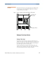
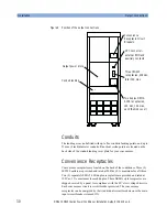


Input Connections
Installation
ONEAC CDR45I Series Power Conditioner, Installation Guide, 913-521 Rev. A
25
4
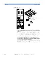
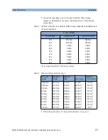
Connect the input phase wires to the input terminals. Phase rotation
sequence is maintained by the power conditioner. Refer to the following
wiring charts:
* Wire insulation rated for 75 ˚C minimum is required.
5
Follow the procedure in
“Verifying the Installation” on page 19
.
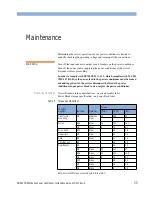
Table 2
Minimum wire sizes (in conduit) for different input voltages and Full Rated Load
of Power Conditioner
Product CDR45I
Input Voltage
Input Wire Size*
Input Grd. Wire Size*
200
#0 AWG
#0 AWG
208
#0 AWG
#0 AWG
240
2 AWG
2 AWG
380
4 AWG
4 AWG
400
4 AWG
4 AWG
415
4 AWG
4 AWG
440
4 AWG
6 AWG
448
4 AWG
6 AWG
480
6 AWG
6 AWG
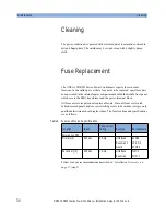
Table 3
Wire size metric conversion chart
Wire Size
(AWG)
Diameter
(MILS)
Diameter
(mm)
Area (mm2)
Standard
Metric (mm2)
0000 AWG
460 MILS
11.7 mm
107 mm
2
110 mm
2
000 AWG
410 MILS
10.4 mm
85.0 mm
2
85 mm
2
00 AWG
365 MILS
9.27 mm
67.4 mm
2
70 mm
2
0 AWG
325 MILS
8.25 mm
53.5 mm
2
60 mm
2
2 AWG
258 MILS
6.54 mm
33.6 mm
2
35 mm
2
3 AWG
229 MILS
5.88 mm
26.7 mm
2
30 mm
2
4 AWG
204 MILS
5.19 mm
21.2 mm
2
25 mm
2
6 AWG
162 MILS
4.12 mm
13.3 mm
2
16 mm
2
8 AWG
128 MILS
3.26 mm
8.37 mm
2
10 mm
2
10 AWG
102 MILS
2.59 mm
5.26 mm
2
6 mm
2
Summary of Contents for CDR45I Series
Page 6: ...Safety Information 6 ONEAC CDR45I Series Power Conditioner Installation Guide 913 521 Rev A...
Page 10: ...List of Figures 10 ONEAC CDR45I Series Power Conditioner Installation Guide 913 521 Rev...
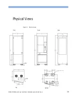
Page 40: ...Physical Views 40 ONEAC CDR45I Series Power Conditioner Installation Guide 913 521 Rev A...


