Specifications
CDR45I Specifications
42
ONEAC CDR45I Series Power Conditioner, Installation Guide, 913-521 Rev. A
Input voltage tap
Factory configured for 400 Vac, unless otherwise labelled on the input power
block. Any mains transformer jumpers required that are not already in use on
the transformer primaries will be shipped inside the unit within the spares
compartment.
Input connections
Prepared for fixed wiring of power line cable to internal power block. Accepts
wire size 6AWG - 350 MCM (16-177 mm
2
)
Adaptable for steel or flexible steel conduit fed from bottom or top of unit (2
inch (51 mm) hole in base or shim or punch to size).
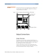
Output connections
Prepared for fixed wiring of power line cable to internal power block. Accepts
wire size 6AWG - 350 MCM (16-177 mm
2
).
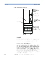
Conduit steel or flexible steel fed from rear of unit (up to five (5) 2 inch (51
mm) holes in conduit landing panel punched as required.)
Convenience outlets
Three (3) IEC 320 outlets rated 120 Vac, 10 A max.
Outlets labeled “1:10A 208 V Max. Output”.
Two (2) NEMA 5-15R duplex outlets rated 120 Vac, 15 A max, each. Covered
with a steel plate for CE compliance.
Outlets labeled: “2: 15 A 120 V Max. Output” and “3: 15 A 120 V Max.
Output”.
Corresponding circuit breakers labeled: “Convenience outlets: 1,2,3”.
Convenience outlets are energized when main input circuit breaker is turned
ON and individual convenience circuit breaker is turned ON.
Main output circuit breaker
Energizes main output power block only.
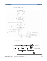
Failsafe EMO
Red mushroom push button remains depressed in activated position until
manually released. Button labeled “EMERGENCY OFF”.
Employs a 24 Vac control circuit powered from an isolation transformer with
dual primaries for various input voltage configurations from 200 to 480 Vac.
The 24 Vac control transformer is energized prior to the main input circuit
breaker. The control circuit is fuse protected on both the primary and secondary
sides.Two (2) spare primary fuses (2A, 600 Vac) and one (1) spare secondary
fuse (1A, 250 Vac) are provided and shipped with the unit in the spares
compartment.
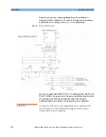
Limited to 1.0 amp. An external normally closed (NC) contact or series string
of NC contacts, can be connected in the series contact circuit by removing the
shorting plug shipped with the unit and connecting across pins J1-3 and J1-4 of
the CPC connector. This CPC connector is located on the back of the
conditioner. A spare mating plug (P1) is supplied with 4 loose pins and one
cable strain relief with each unit in the spares compartment.
Summary of Contents for CDR45I Series
Page 6: ...Safety Information 6 ONEAC CDR45I Series Power Conditioner Installation Guide 913 521 Rev A...
Page 10: ...List of Figures 10 ONEAC CDR45I Series Power Conditioner Installation Guide 913 521 Rev...
Page 40: ...Physical Views 40 ONEAC CDR45I Series Power Conditioner Installation Guide 913 521 Rev A...

