background image

1645

Chapter 2

User manual

Installing and connecting the 1645

12

2

Installing and connecting the 1645

First this chapter gives some important safety instructions. Then it explains how to install and connect 
the 1645.

You are advised to read this chapter from the beginning to the end, without skipping any part. By doing 
so, your 1645 will be completely installed and ready for configuration when you reach the end of this 
chapter.

The following gives an overview of this chapter:

2.1 - Safety instructions / Consignes de sécurité on page 13

2.2 - Unpacking on page 15

2.3 - Selecting a site on page 16

2.4 - Mounting the 1645 on a wall on page 17

2.5 - Mounting the 1645 in a 19” rack on page 19

2.6 - Connection precautions on page 20

2.7 - Connecting the 1645 on page 21

2.8 - The front panel LED indicators on page 27

2.9 - Powering up the 1645 on page 31

Summary of Contents for 1645

Page 1: ...1645 Installation Guide Version 1 5 558499 30 January 2015 ...

Page 2: ...r typographical errors for which OneAccess never can or shall be held liable Changes are made periodically to the information herein these changes will be incorporated in new editions of this publication OneAccess may make improvements and or changes in the product s described in this publication at any time without prior notice Safety requirements Carefully read the safety instructions installati...

Page 3: ...cables de la Directive 1999 5 EC Hiermit OneAccess erklärt daß dieser 1645 in Fügsamkeit ist mit den wesentlichen Anforderungen und anderen relevanten Bereitstellungen von Direktive 1999 5 EC Mediante la presente OneAccess declara que el 1645 cumple con los requisitos esenciales y las demás prescripciones relevantes de la Directiva 1999 5 CE A OneAccess declara que o 1645 cumpre os principais requ...

Page 4: ...ortateur te contacteren Voor Belgie kan u contact opnemen met rma oneaccess net com Le symbole de la poubelle sur roues barrée d une croix signifie que ce produit doit faire l objet d une collecte sélective en fin de vie au sein de l Union Européenne Cette mesure s applique non seulement à votre appareil mais également à tout autre accessoire marqué de ce symbole Ne jetez pas ces produits dans les...

Page 5: ...ormation about all features that can be configured in TDRE i e encapsulations routing bridging QoS tunnels IPSEC The reference part of the TDRE manual contains a complete descrip tion of all the configuration status performance and alarm parame ters for look up purposes The proxy management also called Orchid function parameters are described in the Orchid function manual Maintenance tools user ma...

Page 6: ...is new unit have been carefully and thoroughly tested and inspected If any fault is found with this unit or should you have any other quality related com ment concerning this delivery please submit the Quality Comment Form on our web page at www oneaccess net com Support Quality Comment Form The format indicates Normal normal text Italic new or emphasised words application windows buttons and fiel...

Page 7: ...9 rack 19 2 6 Connection precautions 20 2 7 Connecting the 1645 21 2 8 The front panel LED indicators 27 2 9 Powering up the 1645 31 3 TMA sub system picture 32 4 Technical specifications 34 4 1 SHDSL line specifications 35 4 2 VDSL and ADSL line specifications 36 4 3 ETH1 4 port Ethernet switch specifications 37 4 4 ETH2 ETH3 UTP interface specifications 38 4 5 ETH2 ETH3 SFP interface 39 4 6 USB ...

Page 8: ...1645 User manual 1 Installation Guide ...

Page 9: ...n introduction to the 1645 The following gives an overview of this chapter 1 1 General description on page 3 1 2 1645 Family Overview on page 5 1 3 Versions Mapping on page 6 1 4 Maintenance and management tools on page 7 1 5 Maintenance and management tools connection possibilities on page 11 ...

Page 10: ...Ethernet infrastructure a second Gigabit Ethernet Combo interface can be provided which can be used as backup of the first uplink The 4 port GigE switch provides the inter face to the user applications Extensive Feature Set At the heart of this platform is a high performance Ethernet switch router incorporating advanced Layer 2 and Layer 3 forwarding security and Quality of Service capabilities as...

Page 11: ...hese include TMA GUI application A customisable Web configuration utility A CLI for scripting and simple integration with provisioning and management systems Element and Inventory Management for control and monitoring of large access networks Quality Monitoring And Service Level Agreements The 1645 keeps statistics of the last 15 minutes 2 hours 24 hours and 7 days Selected statistics can be store...

Page 12: ...rview The following gives an overview of the 1645 versions Standard version Gigabit Ethernet combo UTP SFP 4 pair SHDSL bis ATM EFM VDSL 4 port Gigabit Ethernet Switch USB 1645 Gb5TU 1 X X 1645 MGb5TU 1 X X X 1645 2Gb6TU 2 X X 1645 M2Gb6TU 2 X X X 1645 AV2 Gb5TU 1 1 X X ...

Page 13: ... as the commercial name In this table you can find the mapping between the certification name and the commercial name Commercial Name Certification Name 1645 2Gb6TU MB MB90 SLHs1UFPE0SNn RTC LW901G 1645 Gb5TU MB MB90 SLHs1UFPE0SNn RTC 1645 M2Gb6TU MB MB90 SLHs4GI1UFPE0SNn RTC LW901G 1645 MGb5TU MB MB90 SLHs4GI1UFPE0SNn RTC ...

Page 14: ...nd management tools This section gives a quick overview of the various maintenance and management tools that can be used to manage the 1645 The following gives an overview of this section 1 4 1 Overview of various tools on page 8 1 4 2 Upgrading the software on page 10 ...

Page 15: ...ers of OneAccess devices It combines the easy to use graphical inter face of the stand alone version of TMA with an event logging application called the Element Viewer Refer to the TMA Element Management manual PDF CHM for more information TMA CLI TMA CLI TMA Command Line Interface enables you to use its commands in scripts in order to automate management actions This is particularly useful in lar...

Page 16: ...you to add HTML pages on top of the standard Web Interface by adding a set of specific files on the file system of the 1645 These files can be made either by OneAccess or by the customer itself The goal is to offer a simple custom made web interface which allows only to change or show those parameters that are relevant for a certain application or cus tomer Refer to the Maintenance tools manual PD...

Page 17: ...e lowest software level The loader software takes care of the second phase in the start up sequence of the device It is located on the middle software level The application software also called control software or firmware completely controls the device It is located on the highest software level How to upgrade the device software has been described in detail in the TMA Quick Start Guide PDF for u...

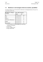
Page 18: ...the maintenance and management tools and how you can connect them with the 1645 Maintenance or manage ment tool Tool 1645 connection Serial IP1 1 An IP connection is a connection between your PC and the 1645 over an IP network CLI X2 2 Using Telnet TMA X TMA CLI X TMA Element Management X SNMP3 3 Using an SNMP browser X Web Interface4 4 Using a web browser X ...

Page 19: ...g so your 1645 will be completely installed and ready for configuration when you reach the end of this chapter The following gives an overview of this chapter 2 1 Safety instructions Consignes de sécurité on page 13 2 2 Unpacking on page 15 2 3 Selecting a site on page 16 2 4 Mounting the 1645 on a wall on page 17 2 5 Mounting the 1645 in a 19 rack on page 19 2 6 Connection precautions on page 20 ...

Page 20: ...tion dans le connecteur d entrée d alimentation correspon dant de l équipement 2 Rebouclez le câble d alimentation autour de la bride de maintien prévue à cet effet sur le pan neau arrière pour éviter l arrachage accidentel du connecteur d alimentation Uniquement pour les équipements qui sont pourvus d une bride de maintien 3 Branchez la fiche d alimentation au réseau d alimentation électrique voi...

Page 21: ...ossible safety hazards caused by differences in earth potentials Pour éviter d endommager l équipement veuillez respecter toutes les procédures décrites dans ce chapitre Débranchez l alimentation de la prise réseau électrique avant d installer déplacer ou inter venir sur l équipement Débranchez toujours l alimentation réseau électrique en premier Assurez vous que l équipement et ses périphériques ...

Page 22: ...ase you need to store the unit or ship it in the future Package content The 1645 package includes the following items for standard items 1645 device External Power Supply with power cord 2 meter This item may be omitted in some cases Stickers printed with the sales item number description serial number and used input voltage The label is attached to the housing and to the outside of the container ...

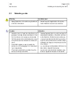
Page 23: ...arance at the back for cables and wires The AC DC adapter is used to switch the device on or off by plugging it in or disconnect ing it respectively The socket outlet shall be installed near the device and easily accessible Installez l appareil dans une zone exempte de températures extrêmes d humidité de chocs et de vibrations Positionnez le de sorte que vous puissiez aisément accéder au panneau a...

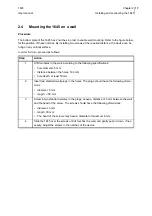
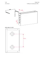
Page 24: ...ding to the following specifications hole diameter 5 mm distance between the holes 160 mm hole depth at least 50 mm 2 Insert two standard wall plugs in the holes The plugs should have the following dimen sions diameter 5 mm length 50 mm 3 Screw in two standard screws in the plugs Leave a distance of 5 mm between the wall and the head of the screw The screws should have the following dimensions dia...

Page 25: ...1645 Chapter 2 User manual Installing and connecting the 1645 18 Bottom plate of the 1645 ...

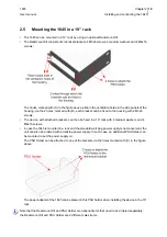
Page 26: ... attached brackets can then be fixed in a 19 rack with 4 medium washers and 4 M6x16 screws In case the 1645 is mounted in a rack and the standard wall plug power supply is not convenient the unit can also be ordered with a desktop power supply In such case an additional PSU Holder can be mounted to put the power supply on The PSU Holder can be attached to one of the brackets via the holes marked w...

Page 27: ...ilding and not subject to telecom network primary nor secondary lightning strikes Outside building circuit Circuit routed going outside building and possibly subject to telecom network secondary lightning strikes SELV or Safety Extra Low Voltage Inside building circuit designed to not exceed safe voltage value TNV or Telecom Network Voltage User s accessible internal circuit designed to not exceed...

Page 28: ...g the 1645 This section describes the 1645 rear panel It identifies the interface type and port numbering and explains how to connect the device The following gives an overview of this section 2 7 1 Rear view of the 1645 on page 22 2 7 2 The different parts of the 1645 on page 25 ...

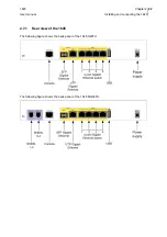
Page 29: ...hapter 2 User manual Installing and connecting the 1645 22 2 7 1 Rear view of the 1645 The following figure shows the back panel of the 1645 Gb5TU The following figure shows the back panel of the 1645 MGb5TU ...

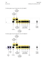
Page 30: ...1645 Chapter 2 User manual Installing and connecting the 1645 23 The following figure shows the back panel of the 1645 2Gb6TU The following figure shows the back panel of the 1645 M2Gb6TU ...

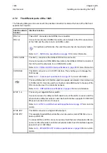
Page 31: ...1645 Chapter 2 User manual Installing and connecting the 1645 24 The following figure shows the back panel of the 1645 AV2 Gb5TU ...

Page 32: ... to manage the 1645 locally Refer to 4 7 Console port specifications on page 41 for more information This is a USB version 2 0 interface and can operate as a master It can deliver up to 1000mA at 5V It can be used to connect a mobile USB device for backup of the DSL connection over the mobile 3G network Refer to 4 6 USB interface specifications on page 40 for more information ETH1 1 4 This is a 4 ...

Page 33: ...de to a local optical network outlet The SFP slot supports speeds of up to 1 Gbps Refer to 4 5 ETH2 ETH3 SFP interface on page 39 for more information 12VDC 3A This is the power input Insert the plug of the external power supply in this socket Secure the power supply connection by installing the DC power supply cord into the plastic ring provided on the back panel Refer to 4 8 Power requirements o...

Page 34: ...g the 1645 27 2 8 The front panel LED indicators This section gives an overview of the front panel LEDs and what they indicate The following gives an overview of this section 2 8 1 Introducing the front panel LEDs on page 28 2 8 2 LED states on page 29 ...

Page 35: ... of the 1645 MGb5TU The following figure shows the front panel LED indicators of the 1645 2Gb6TU The following figure shows the front panel LED indicators of the 1645 M2Gb6TU The following figure shows the front panel LED indicators of the 1645 AV2 Gb5TU LED states One front panel LED can reflect different status modes by the way it lights up The front panel LEDs can light up as follows LED state ...

Page 36: ... is present on the devices equipped with an ADSL2 VDSL interface OFF The DSL interface is not configured ON Red The DSL interface does not get any reaction of the other side of the DSL link on any of the line pairs although it is config ured Blinking green The DSL synchronisation is in progress Less than minActiveLinks are yet synchronised in case of multipair with EFM or IMA ON Green The DSL upli...

Page 37: ...ady for use registered to 3G network Blinking green USB port configured and active connection to the 3G network indication of data traffic AUX For future use 1 An IP interface is a physical or logical interface e g ATM PVC PPP session VLAN IP inter face in a bridge group which is configured for IP traffic routed mode and is not in the admin istrative down status The loopback interfaces softwareLoo...

Page 38: ...o the AC mains Self test A few seconds after the power is switched on the 1645 performs a series of self tests and loads the software into memory RAM during which the PWR LED on the front panel blinks At the end of the software loading after about 30 seconds if the PWR LED remains green continuously it means that the software initialization was successful the PWR LED blinks it means that the softw...

Page 39: ... the sub system picture and how to interpret the visual indications How to display the sub system picture To display the sub system picture of the 1645 click on the sub system picture button located in the TMA toolbar Structure of the sub system picture This paragraph displays and labels the different elements of the sub system picture It also explains how the visual indications should be interpre...

Page 40: ...stem picture corresponds with the LED indication on the 1645 itself Refer to 2 8 The front panel LED indicators on page 27 for more information on the interpretation of the LEDs interfaces on back panel These reflect the status of the interfaces The possible indications are green There is no alarm active in the corresponding interface object red An alarm is active in the corresponding interface ob...

Page 41: ...ge 36 4 3 ETH1 4 port Ethernet switch specifications on page 37 4 4 ETH2 ETH3 UTP interface specifications on page 38 4 5 ETH2 ETH3 SFP interface on page 39 4 6 USB interface specifications on page 40 4 7 Console port specifications on page 41 4 8 Power requirements on page 42 4 9 Dimensions on page 43 4 10 Safety compliance on page 44 4 11 Over voltage and over current protection compliance on pa...

Page 42: ...eps of 128kbps Four pair 768 22784 in steps of 256kbps Handshaking compliant G 994 1 automatic speed negotiation or fixed speed Performance monitoring compliant G 826 errored seconds severely errored seconds unavailability seconds The line connector lay out The following table shows the connector layout of the RJ11 line connector for SHDSL line pair 1 2 The following table shows the connector layo...

Page 43: ...L G dmt bis ITU T G 992 4 ADSL2 ITU T G 992 5 ADSL2plus annex A B ADSL2 Annex M optional ADSL EOC and HLOG attenuation ITU T G 993 1 VDSL ITU T G 993 2 VDSL2 VDSL2 profiles 8a 12a 17a 30a annex A B with ADSL2 fallback VDSL Interop Ikanos and Broadcom UPBO and EL Performance monitoring compliant G 826 errored seconds severely errored seconds unavailability seconds The line connector lay out The fol...

Page 44: ...ss over MDI MDI X for automatic connection to a terminal or switch The following LEDs are available built in on each Ethernet interface connector The following table shows the connector layout of the RJ45 Ethernet LAN interface connectors Colour Description Green left1 1 Defined as looking from the back OFF link inactive ON link active Green right1 OFF no traffic in progress ON traffic in progress...

Page 45: ...on to a terminal or switch The following LEDs are built in on the Ethernet interface connector The following table shows the connector layout of the RJ45 Ethernet LAN interface connectors Colour Description Green left1 1 Defined as looking from the back OFF link inactive ON link active Green right1 OFF no traffic in progress ON traffic in progress Pin Signal 10 100 BASE T DTE DCE Signal 1000 BASE ...

Page 46: ...5 SFP 100BASE LX50 100 SM 2FO 50 SFP 100BASE BX101 100 SM 1FO 10 SFP 100BASE BX201 1 Modules for single fibre must be used in pairs BX at one side and BX D at the other side of the link 100 SM 1FO 20 SFP 100BASE BX401 100 SM 1FO 40 SFP 1000BASE SX2 2 Only Gbit Ethernet SFP modules can be used on versions with a Fibre SFP Gbit Ether net interface do not use Fast Ethernet SFP modules in a Gbit SFP s...

Page 47: ... Standard Type A USB connector USB version 2 0 interface The USB interface can operate as a master The USB master interface can deliver up to 1000mA at 5V The following table shows the connector layout of the USB connector Pin Signal Function Figure 1 Vcc 5V 2 D Data 3 D Data 4 GND Ground ...

Page 48: ...parity 1 stop bit The following table shows the connector layout of the RJ45 Console connector A console cable for device configuration and maintenance only requires TX RX and GND to be con nected refer to Annex A Console cable on page 48 for more information about the cable Pin Abbreviation DCE Figure 1 TX Out 2 RX In 3 GND 4 NC 5 NC 6 NC 7 NC 8 NC ...

Page 49: ...Vdc power supply Switched Power Module Input 18 60 Vdc Output 12 Vdc 2 9 A 35W Limited Power Source LPS Do not use another type of power supply than the one recommended by OneAccess 4 9 Dimensions The 1645 has a metal housing with the following characteristics Width 275 mm Height 55 mm Depth 146 mm Total weigh of the device 1 26 kg The weight of the external power adaptors is as follows Descriptio...

Page 50: ...0 3 3 Voltage fluctuations and flicker EN61000 4 2 ESD EN61000 4 3 Radiated immunity EN61000 4 4 EFT burst EN61000 4 5 Surge EN61000 4 6 Conducted immunity EN61000 4 8 Power magnetic field immunity EN61000 4 11 Voltage dips drops EN300386 EMC Requirements 4 13 Environmental compliance Storage conditions ETSI ETS 300 019 1 1 Class 1 1 In addition the storage temperature has to be between 25 to 70 C...

Page 51: ...1645 Annex 47 Annex ...

Page 52: ...1645 Annex A Annex Console cable 48 Annex A Console cable Standard console cable The following figure shows the console cable assembly it has reference code 501288 ...

Page 53: ... SFP interface specifications 39 ETH2 UTP interface specifications 38 F feedback vi I installing and connecting the device 12 introducing maintenance and management tools 7 the device 3 introduction 2 L LED indicators 27 introduction 28 LED states 29 line specifications 35 36 connector lay out 36 M maintenance and management connection possibilities 11 maintenance and management tools introducing ...

Page 54: ...44 power requirements 42 safety compliance 44 USB interface 40 statements iii T TDRE version vi what is vi technical specifications 34 TMA sub system picture 32 how to display 32 structure 32 U unpacking 15 USB interface specifications 40 V versions mapping 6 W wall mounting 17 warning ESD 20 ...

Reviews: