6
Oneida Air Systems, Inc.
Assembly Instructions
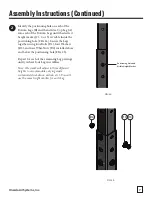
FIG. 1a
FIG. 1b
THE TELESCOPING STAND SHOULD BE INSTALLED ON A FLAT, STABLE BASE CAPABLE OF SUPPORTING
THE WEIGHT OF THE ENTIRE SYSTEM (INCLUDING FULL WASTE CONTAINERS) ONCE ASSEMBLED.
1
Determine the location and orientation for
your installation, taking careful note of which
direction the dust collector’s inlet and filter
plenum will be facing [FIG. 1a].
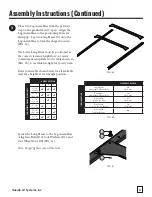
Depending on your system's configuration,
refer to the table shown in [FIG. 1b] for the
Recommended Leg Position.
Note: We recommend that the stand be
assembled laying down and then raised into
position later on.
REQUIRED TOOLS
RECOMMENDED TOOLS
9/16" Wrench
Impact Driver
Leveling Tool
9/16" Socket Wrench
2x4 Blocks
Torque Wrench
* You will need to supply your own mounting hardware if you wish to secure the Stand or Filter Option to the surface you are
mounting it onto (e.g. screws, washers, lag bolts, nuts, etc.).
LEG POSITION RECOMMENDED
SY
STEM
C
ONFIGURA
TION
21" Cyclone
5 HP SMART
23" Cyclone
5 HP & 7.5 HP
28" Cyclone
10 HP
Single Drum
with/without Drum Dolly
Position 1
Position 1
Position 1
Dual Drum
with/without Drum Dolly
Position 2
Position 2
Position 2
Airlock with
1 Cu. Yd. Hopper
Position 2
Position 2
Position 2
Airlock with
1-1/2 or 2 Cu. Yd. Hopper
Position 3
Position 3
Position 3
Airlock with
Transfer Blower
ANY
ANY
ANY


