8
Oneida Air Systems, Inc.
Assembly Instructions (Continued)
3
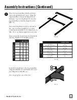
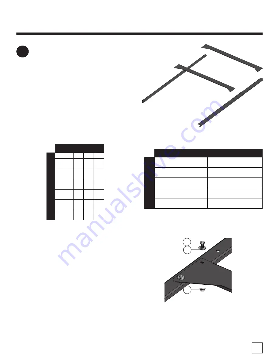
Place two Leg Assemblies from the previous
step on the ground about 5' apart . Align the
Leg Assemblies so the positioning holes are
facing up. Lay two Long Braces (C) onto the
Leg Assemblies to form the shape shown in
[FIG. 3a].
The Lower Long Brace must be positioned at
the correct clearance height for your waste
containment setup. Refer to the table shown in
[FIG. 3b] to see which is right for your system.
Refer to the table shown below for all available
clearance heights at each height position.
Secure the Long Braces to the Leg Assemblies
using four Bolts (D2), four Washers (D3), and
four Whiz-Nuts (D4) [FIG. 3c].
Note: Finger tighten only at this time.
FIG. 3a
FIG. 3c
FIG. 3b
D2
D3
D4
HEIGHT POSITION
COMP
ATIBLE
CLEARANCE
HEIGHT
S
1
2
3
37-7/8"
962 mm
42-7/8"
1089 mm
47-7/8"
1216 mm
51-7/8"
1318 mm
56-7/8"
1445 mm
61-7/8"
1572 mm
CLEARANCE NEEDED
CONFIGURA
TION
Single Drum
with/without Drum Dolly
40"
1016 mm
Dual Drum
with/without Drum Dolly
40"
1016 mm
Airlock with
1 Cu. Yd. Hopper
43"
1092 mm
Airlock with
1-1/2 or 2 Cu. Yd. Hopper
50"
1270 mm
Airlock with
Transfer Blower
N/A


