background image

5

EXTRA HARDWARE INCLUDED FOR YOUR CONVENIENCE. ITEMS ARE NOT SHOWN TO SCALE.

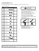
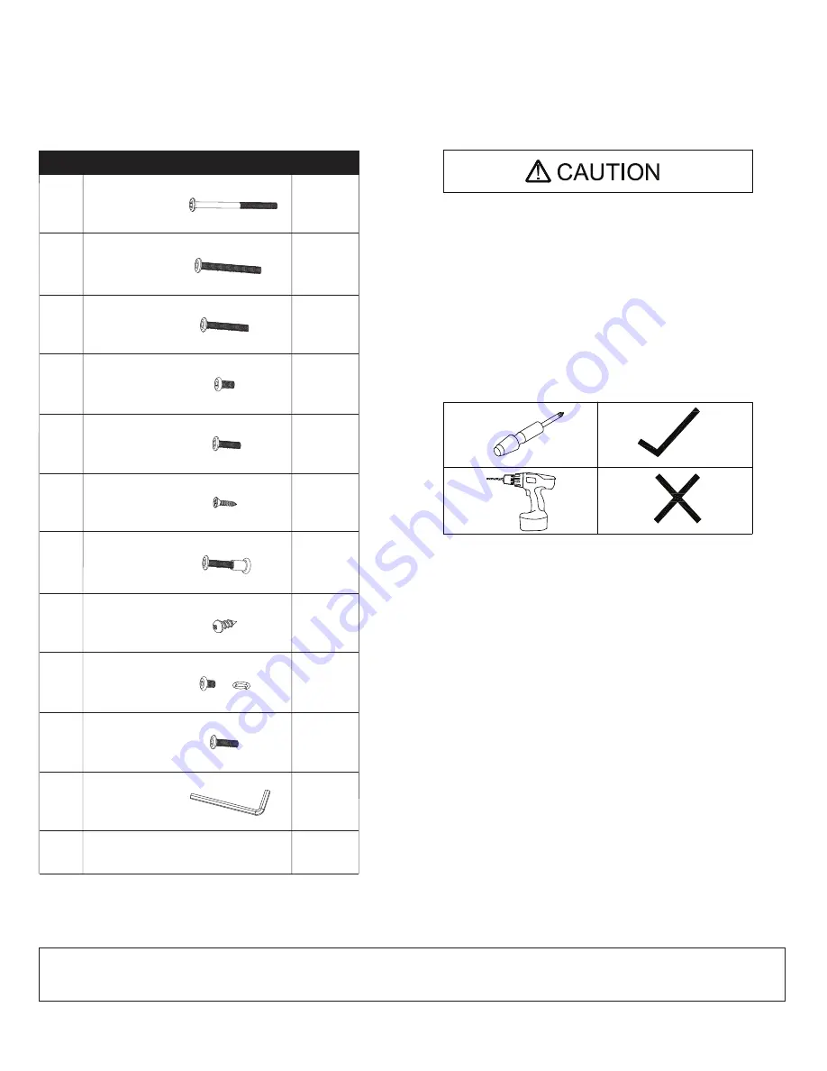
HARDWARE LIST

- READ THE INSTRUCTION MANUAL BEFORE ASSEMBLING.
- REMOVE ALL PIECES BEFORE BEGINNING INSTALLATION.
- OPEN THE HARDWARE AS NEEDED .
- ASSEMBLE IN AN AREA WITH PLENTY OF SPACE.
- READ EACH STEP BEFORE BEGINNING CONSTRUCTION.

- HAVE A SCREWDRIVER BEFORE YOU BEGIN ASSEMBLING 

  (NOT INCLUDED).

- NEVER FORCE THE SCREWS OR FITTINGS.
- KEEP THIS MANUAL FOR FUTURE REFERENCE.
- TIGHTEN ALL THE SCREWS EVERY 6 MONTHS.

CLEANING AND CARE

- CLEAN SURFACES WITH A DRY OR DAMP CLOTH.

- DO NOT USE ABRASIVE CLEANERS.

- DO NOT USE A POWER DRILL.

IF YOU ARE MISSING ANY OF THESE PARTS, OR IF YOU HAVE A DAMAGED PART, PLEASE VISIT WWW.COMFORTPRODUCTS.NET/SUPPORT 

REFERENCE THE MODEL # ON THE FRONT OF THIS MANUAL. SIMPLY COMPLETE THE INFORMATION, INCLUDING THE PART YOU NEED. THE 

PART WILL NORMALLY BE SHIPPED WITHIN 48 HOURS.  

A

B

C

D

E

4

8

4

24

8

4

4

4

1

3

1

STOCK # 51-JN15

L

05HA

DESCRIPTION

F

G

H

I

J

Extra Hardware Set

M6 x 80mm

M6 x 55mm

M6 x 35mm

M6 x 12mm

M6 x 21mm

M6 x 7mm

M6 x 25mm

1

K

Allen Wrench

M4 x 14mm

M6 x 35mm

M4 x 14mm

QTY.

Summary of Contents for 50-JN15L05

Page 1: ...r fastest service on claims requests for replacement parts www comfortproducts net support e mail customerservice comfortproducts net Keep your sales receipt as documentation of your ownership CUSTOME...

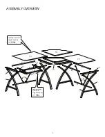
Page 2: ...Desktop maximum weight capacity 130 lbs Keyboard tray maximum weight capacity s b l 10 ASSEMBLYOVERVIEW 2 5 12 11 1 2 6 16 17 9 9 13 14 13 8 3 15 7 10 10 2 1...

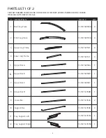
Page 3: ...4 5 6 Upper Bar A 51 JN15L05BA 1 Upper Bar B 51 JN15L05BB 1 7 Upper Bar C 51 JN15L05BC 1 1 3 8 Upper Bar D 51 JN15L05BD 2 9 Lower Bar 51 JN15L05LB 4 10 Support Bar 51 JN15L05SB 1 11 Tray Support Left...

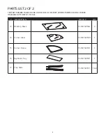
Page 4: ...JN15L05GL 2 14 Corner Glass 51 JN15L05CG 1 15 Keyboard Tray 51 JN15L05KT 1 16 Corner Frame 51 JN15L05CF 1 4 THE PART NUMBER CAN BE FOUND ON THE SIDE OF THE PART EITHER STAMPED OR ON A STICKER ITEMS A...

Page 5: ...IGHTEN ALL THE SCREWS EVERY 6 MONTHS CLEANING AND CARE CLEAN SURFACES WITH A DRY OR DAMP CLOTH DO NOT USE ABRASIVE CLEANERS DO NOT USE A POWER DRILL IF YOU ARE MISSING ANY OF THESE PARTS OR IF YOU HAV...

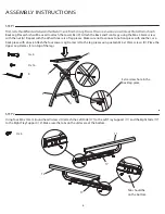
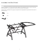
Page 6: ...back piece with a back Attach the four Lower Leg Frames 4 to the leg pieces using sixteen M6 x 12mm screws D Place the Upper Leg Frames 3 on top of the legs STEP 2 Using four M4 x 14mm round head scre...

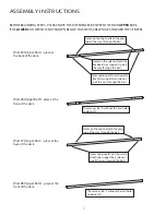
Page 7: ...D place at the front of the desk Holes on the top to attach the glass go all the way through the bar Holes on the side to attach the keyboard tray supports go all the way through the bar Holes undern...

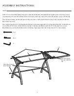
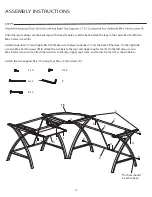
Page 8: ...he tab at the corner of the corner frame faces up even with the top M6 x 55mm screws B K A x 2 B x 4 These holes should be at the back This tab should be even with the top B 5 15 6 3 9 B B B A A Next...

Page 9: ...D Use the outer holes on Upper Bar A You may need to rotate the bar so that the outer holes are facing down Attach the Left 11 and Right 12 Tray Supports to Upper Bar A 5 and Upper Bar B 6 using four...

Page 10: ...sure to place Upper Bar C 7 at the back of the desk On the right side use two M6 x 55mm screws B to attach the two bars to the legs and Upper Leg Frame 3 On the left side use two M6 x 80mm screws A t...

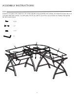
Page 11: ...to the Upper Bars using eight M6 x 21mm Screws E Attach the Corner Glass 14 using three M6 x 25mm Screws J and the M6 x 7mm Screw with the nut I The screw with the nut should go through the tab at the...

Page 12: ...not cover the cost of transportation or labor In no event shall Comfort Products be liable in either tort or contract for any loss or direct special incidental consequential or exemplary damages This...

Reviews: