background image

4

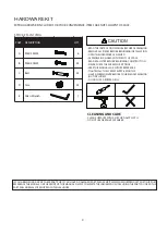
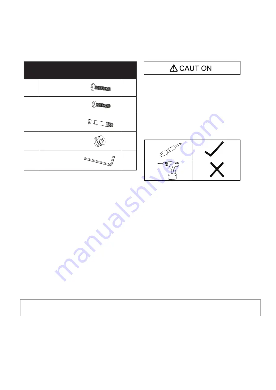
EXTRA HARDWARE INCLUDED FOR YOUR CONVENIENCE. ITEMS ARE NOT SHOWN TO SCALE.

HARDWARE KIT

PART DESCRIPTION

QTY.

A

M6 X 30MM

Bolt

Cam

24

C

D

E

24

24

- READ THE INSTRUCTION MANUAL BEFORE ASSEMBLING.
- REMOVE ALL PIECES BEFORE BEGINNING INSTALLATION.
- OPEN THE HARDWARE AS NEEDED .
- ASSEMBLE IN AN AREA WITH PLENTY OF SPACE.
- READ EACH STEP BEFORE BEGINNING CONSTRUCTION.

- HAVE A SCREWDRIVER BEFORE YOU BEGIN ASSEMBLING 

  (NOT INCLUDED).

- NEVER FORCE THE SCREWS OR FITTINGS.
- KEEP THIS MANUAL FOR FUTURE REFERENCE.
- TIGHTEN ALL THE SCREWS EVERY 6 MONTHS.

CLEANING AND CARE

- CLEAN SURFACES WITH A DRY OR DAMP CLOTH.

- DO NOT USE ABRASIVE CLEANERS.

- DO NOT USE A POWER DRILL.

Allen Wrench

B

1

IF YOU ARE MISSING ANY OF THESE PARTS, OR IF YOU HAVE A DAMAGED PART, PLEASE VISIT WWW.COMFORTPRODUCTS.NET/SUPPORT 

REFERENCE THE MODEL # ON THE FRONT OF THIS MANUAL. SIMPLY COMPLETE THE INFORMATION, INCLUDING THE PART YOU NEED. THE 

PART WILL NORMALLY BE SHIPPED WITHIN 48 HOURS.

M6 X 35MM

6

STOCK # 51-JN173HA

Summary of Contents for 50-JN173SHLF05

Page 1: ...or fastest service on claims requests for replacement parts www comfortproducts net support e mail customerservice comfortproducts net Keep your sales receipt as documentation of your ownership CUSTOM...

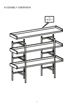
Page 2: ...ASSEMBLY OVERVIEW Shelf weight capacity 110 lbs 2...

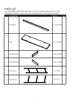
Page 3: ...E SIDE OF THE PART EITHER STAMPED OR ON A STICKER ITEMS ARE NOT SHOWN TO SCALE NOTE THAT THE BOARDS BELOW ARE SHOWN UPSIDE DOWN Back Board 51 JN17305BB Shelf Left Side Board Back Frame 51 JN17305SH 51...

Page 4: ...RE YOU BEGIN ASSEMBLING NOT INCLUDED NEVER FORCE THE SCREWS OR FITTINGS KEEP THIS MANUAL FOR FUTURE REFERENCE TIGHTEN ALL THE SCREWS EVERY 6 MONTHS CLEANING AND CARE CLEAN SURFACES WITH A DRY OR DAMP...

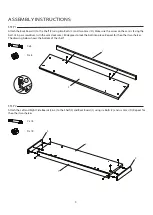
Page 5: ...rrow on the cam is facing the bolt Using a screwdriver turn the cam clockwise 180 degrees to lock the bolt into place Repeat for the other two shelves The drawing below shows the bottom of the shelf A...

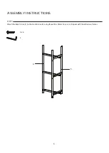
Page 6: ...5 6 ASSEMBLY INSTRUCTIONS 6 STEP 3 E A x 6 Attach the Back Frame 5 to the Front Frame 6 using three M6 x 35mm Screws A Repeat with the other two frames...

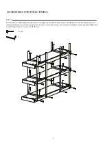
Page 7: ...ASSEMBLY INSTRUCTIONS 7 STEP 4 E B x 24 Attach the assembled shelves to the frames using twenty four M6 x 30mm Screws B Note that in the drawing below the according to which screws you are fastening...

Page 8: ...t subject to defects caused by improper assembly or disassembly defects occurring after purchase due to product mo sure to the elements labor or assembly cost This warranty does not cover the cost of...

Reviews: