background image

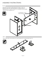
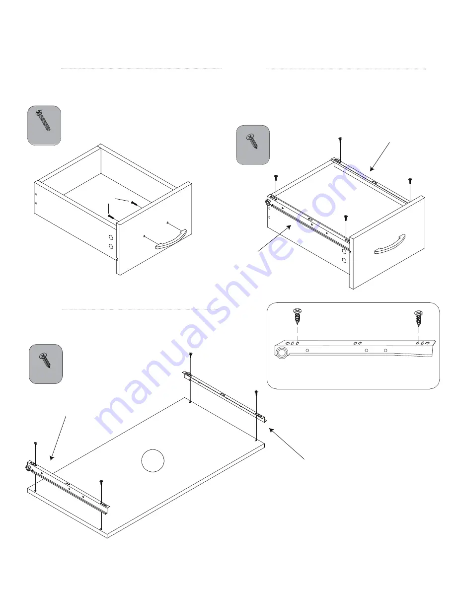
21b, right

21b, right

21b, left

21b, left

B x 2

C x 4

STEP 16

Attach two inner drawer rollers (21b), one left and one 

right, to the bottom of drawer using four screws (C) as shown. 

Make sure rollers are oriented to the back of the drawer. 

Refer to drawing below for which holes in the roller to use.

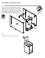
STEP 15

Attach drawer handle (F) to drawer front using

two screws (B). 

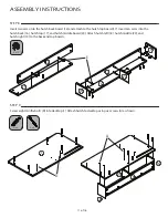
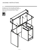
STEP  17

Attach two inner drawer rollers (21b), one left and one right, 

to the bottom of the keyboard tray (7) using four screws (C).

THIRD TO

LAST HOLE

THIRD 

HOLE

7

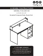
ASSEMBLY INSTRUCTIONS 

14 of 16

B

F

C x 4

Summary of Contents for Essential 50-LD01CO

Page 1: ...CO SUPPLIER CODE JNFF For fastest service on claims requests for replacment parts www comfortproducts net support e mail customerservice comfortproducts net Keep your sales receipt as documentation of...

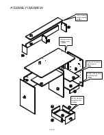
Page 2: ...RVIEW 2 of 16 Desktop maximum weight capacity 165lbs Middle shelf maximum weight capacity 22lbs Drawer maximum weight capacity 11lbs Hutch maximum weight capacity 22lbs Bottom shelf maximum weight cap...

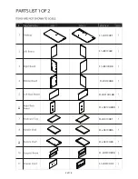
Page 3: ...3 of 16 51 LD01CODT 51 LD01COLB 51 LD01CORB 51 LD01COMB 51 LD01COLBB 51 LD01CORBB 51 LD01COKT 51 LD01COMS 51 LD01COBS 51 LD01COSPB 51 LD01CODF...

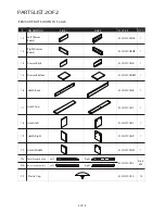
Page 4: ...CORDB 1 14 Drawer Back 51 LD01CODB 1 15 Drawer Bottom 51 LD01CODBM 1 16 Hutch Back 51 LD01COHB 1 17 Hutch Top 51 LD01COHT 1 18 Hutch Left 51 LD01COHL 1 19 Hutch Right 51 LD01COHR 1 20 Hutch Middle 51...

Page 5: ...D WITHIN 48 HOURS READ THE INSTRUCTION MANUAL BEFORE ASSEMBLING REMOVE ALL PIECES BEFORE BEGINNING INSTALLATION OPEN THE HARDWARE AS NEEDED ASSEMBLE IN AN AREA WITH PLENTY OF SPACE READ EACH STEP BEFO...

Page 6: ...ASSEMBLY INSTRUCTIONS 6 of 16 STEP 1 Use a hammer to attach foot pins G to the bottom of the left 2 middle 4 and right 3 boards H x 4...

Page 7: ...o the right board 3 using small screws C Attach two rollers to the middle board 4 a right outer roller 21a to the left side and a left outer roller 21a to the right side Refer to drawing below for whi...

Page 8: ...D x 20 8 of 16 ASSEMBLY INSTRUCTIONS STEP 3 screw Do not overtighten bolts or cams will not lock properly Left Side Right Side...

Page 9: ...into First attach shelf and support boards to the middle board 4 and then attach these to the right board 3 by aligning the bolts and cams With a screwdriver turn the cams about 1 2 turn clockwise to...

Page 10: ...h left board 18 and hutch right board 19 STEP 6 Insert four cams E into the left back board 5 Make sure arrows are facing the smaller holes Attach back board 5 to left board 2 and middle board 4 Turn...

Page 11: ...7 Insert ten cams into the hutch back 16 hutch top 17 and hutch middle board 20 Attach hutch left 18 hutch middle 20 and hutch right 19 to the back and top boards STEP 9 Screw eight minifix bolts D in...

Page 12: ...iddle and right boards and left back board as shown Attach desktop 1 with hutch to the lower part of the desk by aligning the eight bolts D already screwed into the desktop with cams Tighten cams 1 2...

Page 13: ...drawer boards using four screws A D x 4 STEP 13 Insert drawer bottom 15 into grooves STEP 11 STEP 12 Insert cams into the left 12 and right 13 drawer boards and attach both boards to the drawer front...

Page 14: ...sure rollers are oriented to the back of the drawer Refer to drawing below for which holes in the roller to use STEP 15 Attach drawer handle F to drawer front using two screws B STEP 17 Attach two inn...

Page 15: ...rts H into any of the four sets of holes according to desired height Place middle shelf 8 on supports Align inner and outer rollers to insert drawer and keyboard tray Place plastic caps 22 over cams a...

Page 16: ...use and is not subject to defects caused by improper assembly or disassembly defects occurring after purchase due to product mo sure to the elements labor or assembly cost This warranty does not cove...

Reviews: