background image

5

6

The BANJO/TOOLREST BASE is 

ONEWAY's 

own proven design that

assures even, powerful locking anywhere on the bed (patented feature).
The sliding cam is supported by a cam support block which rests on a
ledge machined in the toolrest base. To ensure continuing smooth oper-
ation, lubricate the mechanism whenever it seems to be getting sticky.
The banjo handle will clamp either to the left or right. Generally the
handle is adjusted so that when it is clamped, the handle is clear of the
bed. This allows the banjo to be clamped in all positions over the bed.
The clamp handle position can be adjusted via the Nylock Nut, under-
neath the banjo.

How do I adjust the Toolrest clamp lever?

The toolrest clamp lever can be adjusted to clamp in any position. To
change the position of this lever, unscrew the four screws that hold the
clamp nut in place, rotate it to the desired position and re-fasten the nut
with the screws. Note that there are eight holes in the clamp nut, allow-
ing adjustments of 1/8 rotational increments. The handle clamp position
is an individual preference, but the 4 O’clock position is a good place to
start.

Banjo - Toolrest Base

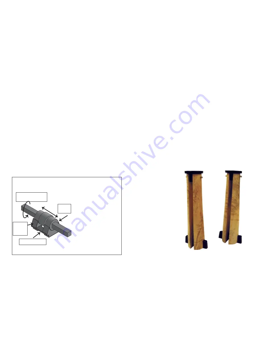
What is a sliding Cam assembly?

This assembly consists of: a rotating square shaft, a short sliding cam and a
support block for the sliding cam. The square shaft rotates the sliding cam.

The cam is supported on a cam support block

which in turn is supported on a
ledge machined in the tool rest
base. The block moves with the
sliding cam and supports the
shaft. Deflection of the cam shaft
is eliminated and there is no
longer a clamping difference
anywhere on the lathe bed.
Unclamp is always at the 12
o’clock position and clamping
may be adjusted to be repeatable
anywhere between 10 & 6

o’clock  with RH and LH clamping always at the same angle.

Cam

Support

Block

Rotating Square 

Shaft

Sliding

Cam

Support Ledge

There are four spindle bearings in the headstock. These bearings are sealed
and lubricated from the factory and should never need adjustment or lubri-
cation. The bearings and the spindle in your lathe are designed to take nor-
mal woodturning forces for a long time. The best way to ensure long bearing
life is to never hammer against the spindle.
Due to the size and the preload on the bearings  the lathe may run quite warm
when it is new. As the bearings break in they will run cooler but will still get
warm. Each lathe is run in at the factory and checked for excess temperatures,
but it is a good idea to keep the speed below 2000 rpms for the first 30 hours
of operation. This allows excess grease in the bearings to escape and for the
seals to break in. When replacing the bearings it is best to replace the front
bearings with a matched set from ONEWAY Mfg. The rear bearings can be
replaced by any equivalent bearing.

Replacing the Bearings

To replace the bearings you must remove the spindle. The first step is to take
the belt off the motor pulley.  Remove the nut on the back side of the spin-
dle and slide off the pulley. Remove the six bolts in the spindle nose cap. Grab
the nose cap and the entire
spindle assembly should
slide out.  If it is tight, take
two of the bolts you just
removed and put them into
the two tapped holes in the
nose cap. Tighten them alter-
nately and this will jack out
the spindle. If you do not have
a proper set of bearing tools, it
is a good idea to send the spin-
dle back to ONEWAY to pre-
vent damage to the spindle
and to the new bearings. 

Bearings

Candle Holders
by Christian Burchard

Summary of Contents for 1224

Page 1: ...arings The Tailstock Assembly and Set Up The Drive Control Description Common Problems How to Avoid Them If The Drive Does Trip Out Maintenance and Lubrication Changing the Belt Attaching Removing Accessories From the Spindle Indexing General Safety Accessories Manufacturers Limited Warranty Appendix Wiring Diagram M0185 Banjo Assembly M0181 Tailstock Assembly M0220 Headstock Assembly M0219 Spindl...

Page 2: ...instruction will ensure that you work safely and that you can use your new lathe at it s optimum ONEWAY 1224 LATHE MANUAL Other Specifications 3 Bedways and ribs are welded to a 4 1 2 inch diameter 1 4 inch wall tube The assembly is stress relieved and precision machined Bedways are offset so chips and debris fall straight thru without sacri ficing rigidity Almost perfect torsional rigidity is ach...

Page 3: ...the 12 o clock position and clamping may be adjusted to be repeatable anywhere between 10 6 o clock with RH and LH clamping always at the same angle Cam Support Block Rotating Square Shaft Sliding Cam Support Ledge There are four spindle bearings in the headstock These bearings are sealed and lubricated from the factory and should never need adjustment or lubri cation The bearings and the spindle ...

Page 4: ... Use an 11 mm wrench to loosen the two nuts attaching the lathe to the shipping shelf If the carriage bolts don t fall through tap them through These bolts are not required later Cut the cable ties attaching the electrical box to the lathe bed and remove the lathe from inside the bench Step 2 Attach the Pendant Brackets Inside the bench there are two pendant brackets Attach these to the top of the...

Page 5: ...three slotted holes will have washers and nuts one round hole will have a nut only Position the lathe so the holes in the bottom of the lathe assembly line up with these holes Starting with the hole in the left front use one bolt and one nut to fasten the lathe to the bench this step is easiest with the motor in the down position Continue clockwise bolting the lathe onto the bench Step 9 Attach th...

Page 6: ...f the drive system it will shut itself down and the motor will coast to a stop If this happens the lathe will not respond to any input from the pendant control To reset the Drive turn the power off LET THE LATHE SIT FOR 30 SECONDS and then turn the power back on Common Problems How to Avoid Them ONEWAY Lathes like any mechanical device needs lubrication to function at its optimum Woodturning creat...

Page 7: ...Y Lathes are very heavy solid machines and can rotate pieces faster than most other lathes ONEWAY Lathes are also very quiet and it is easy to run the lathe faster than you think it is going Bark shavings and pieces of wood can fly from the lathe with considerable force unexpectedly at any time Always wear face protection to prevent injury in such instances Safety glasses will not protect your who...

Page 8: ...econnected 17 The Tool Rest adjust the tool rest height properly adjust the tool rest so that it is as close to your work piece as possible remove the tool rest when sanding or buffing 18 When roughing always work downhill roughing from large to small diameters LATHE BED EXTENSION A 24 extension which bolts onto the end of the 1224 is available which increas es the distance between centres from 24...

Page 9: ...modified in any way 4 The product has not been subjected to misuse abuse negligence or was not used in a normal manner 5 All transportation costs incurred in returning the product to Oneway Manufacturing is pre paid by the customer 6 Defective parts will be returned using the Candian or U S Postal Service ground or relevant Postal Service surface if overseas packaged appro priately and labelled De...

Page 10: ... Item File Name Title Qty 1 M0044 par Lock Handle 1 2 M0046 par 5 16 dowel 1 3 M0041 par Lock Handle 1 4 M0040 par Lock Screw 1 5 M6 x 16 bhcs par M6 x 16 bhcs 2 6 5 x 16 shcs par m5 x 16 shcs 4 7 M6 falt washer par M6 flat washer 2 8 M0042 par Boss Hex Broached 1 9 M0039 par Lock Pad Threaded 1 10 M0165 banjo par Banjo machined 1 11 M0031 par Pressure Pad 1 12 M0034 PAR Eccentric bushing 1 13 M00...

Page 11: ...20 M0053 21 5 16 x 1 1 2 shoulder bolt 22 M0122 1 2 3 4 5 6 7 8 M0220 M0220 Item Part Title Quanti ty 1 Jam nut par 3 4 16 nut 1 2 M0171 par pulley 1 3 M0072 par Index Pin 1 4 M0161 par headstock 1 5 M0071 par Lock screw 1 6 M0219 asm spindle assy 1 7 AB172b Key 405 1_8 x 5_8 par Key Key No 405 1 8 x 5 8 ANS B 17 2 1 8 M6 X25 BHCS par M6 X 25 BHCS 6 Part No M0220 For Assy 12 x 24 mini Oneway Mfg T...

Page 12: ... M0179 par spacer 1 9 M0018 par spacer 1 10 Bearing rear par 6204LLBC3 2 11 M0080 par rear brg spacer 1 Part No M0219 For Assy M0220 Oneway Mfg Title Spindle Assy Material Date 2 8 02 tolerance unless otherwise specified fractional 03 decimal xx 01 XXX 005 1 2 3 4 6 7 8 1 8 5 M0195 11 Item File Name Title Qty 1 8 32 x 50 par 8 32 x 5 4 2 M0197 psm Plate 1 3 M0193 psm Back Plate 1 4 Latch par Sprin...

Page 13: ...x bolt M6 hex nut 1 4 x 3 4 keystock M6 x 20 hex head bolt washer PART NO M0083 TITLE MOTOR BRACKET ASSY ONEWAY MFG motor to elec box cable 14 4 type SJ cable 40 long M8 hex nut M0085 3 8 washer 2 req 3 8 x 3 4 hex bolt 4 req M0083 3 8 hex jam nut view from spindle end 3 8 x 1 1 4 shcs 2517 2 REQ M0087 M0086 ...

Reviews: