


Process Flow Rate 4-20mA Analog Output
The 4-20mA output of the FT4X HART represents the process flow rate measurement, linearized
and scaled according to the configured range of the instrument. This output corresponds to
the Primary Variable. HART Communication is supported on this loop.
The 4-20mA output of the FT4X should be configured for flow rate when using HART. If the
4-20mA output is set to report temperature, HART communication will report the 4-20mA
value for temperature rather than flow.
HART Indicators
Green LED indicator LP3 cycles on and off to indicate that the FT4X is operating. Orange LED
indicator LP2 blinks when HART signals are received and Yellow LP1 blinks when HART signals
are transmitted. The LEDs are located behind the display panel.
The orange LED indicator LP2 will be on continuously when HART communication is enabled
and the 4-20mA wiring is not connected.
FT4X HART Communication Setup
HART communication must be selected in the FT4X Serial Communication menu for HART
communication to operate. When this communication parameter is changed, power to the
FT4X must be cycled for it to take effect.
Communication Protocol and Parameters
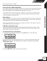
To program the communication parameters, press
I/O (F1)
key from the Main Menu.
F1 F2 F3 F4
This is the Main Menu for the programming mode. To exit the programming mode, press
EXIT (F4)
repeatedly until “Normal Mode” is seen briefly. Choose I/O (F1) to access the
communication output.
F1 F2 F3 F4
Then press
COM (F1)
to select communication parameters.
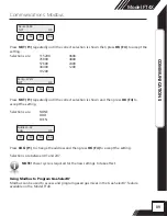
MAIN MENU
I/O FLO DSP EXIT
SET I/O
COM PUL 420 EXIT
93
Model FT4X
COMMUNICA
TIONS
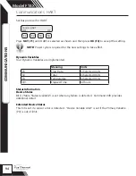
Communications: HART


