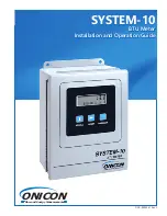
background image

 ON

I

CON

Flow and Energy Measurement

SYSTEM-10

SYSTEM-10

BTU Meter

BTU Meter

Installation and Operation Guide

Installation and Operation Guide


DOC-0002341 Rev.C

Summary of Contents for SYS-10-1110-01O1

Page 1: ...ONICON Flow and Energy Measurement SYSTEM 10 SYSTEM 10 BTU Meter BTU Meter Installation and Operation Guide Installation and Operation Guide DOC 0002341 Rev C ...

Page 2: ...d party is harmed by the use of this product ONICON Incorporated assumes no responsibility for any such harm owing to any defects in the product which were not predictable or for any indirect damages SAFETY PRECAUTIONS The following general safety precautions must be observed during all phases of installation operation service and repair of this product Failure to comply with these precautions or ...

Page 3: ...2 Thermowell Installation 14 3 2 2 1 Dry Tap Thermowells 14 3 2 2 2 Hot Tap Thermowells 14 3 2 3 Temperature Sensor Installation 17 3 2 4 Flow Meter Installation 17 3 3 ELECTRICAL INSTALLATION 18 3 3 1 Input Power Requirements 18 3 3 2 Input Signal Connections 19 3 3 2 1 Input Signal Connections from Temperature Sensors 19 3 3 2 2 Input Signal Connections From F 1000 Series Flow Meters 20 3 3 2 3 ...

Page 4: ...eet 35 SECTION 5 0 DIAGNOSTICS 36 5 1 DIAGNOSTICS 36 5 1 1 Diagnostic Lights 36 5 1 2 Flow Test Signals 36 5 1 3 Temperature Test Signals 36 5 2 ALARM STATUS MENU PAGE 37 5 3 TROUBLESHOOTING 38 APPENDIX A DRAWINGS 39 OUTDOOR THERMOWELL ASSEMBLY IN WELDED PIPE A 1 HEAVY DUTY THERMOWELL ASSEMBLY FOR PROCESS TEMPERATURES OVER 300 F A 2 3 SYSTEM 10 BTU METER MOTHER BOARD A 4 SYSTEM 10 BTU METER COMM B...

Page 5: ...ta and displays and or transmits the results as an indication of the amount of heat BTU s being transferred per unit time or as a totalized amount WARNING Only qualified service personnel should attempt to install or service this product Serious injury may result from the improper Installation or use of this product SYSTEM 10 SENSOR TEMPERATURE RETURN TEMPERATURE SUPPLY SENSOR HEAT EXCHANGER RETUR...

Page 6: ...ee 1 4 MODEL NUMBERING SYSTEM for more details INPUT POWER 24 VAC 20 28 VAC 50 60 Hz 12 VA 120 VAC 108 132 VAC 50 60 Hz 15 VA 240 VAC 207 253 VAC 50 60 Hz 15 VA I O SIGNAL ISOLATED SOLID STATE DRY CONTACT PULSE OUTPUT S Three 3 pulse outputs available Mode 1 scaled pulse output for Energy Total Mode 2 scaled pulse output for Energy Total Mode Status indicates mode 1 or mode 2 operation Contact rat...

Page 7: ...SIGNALS Use 18 22 ga twisted shielded pair FLOW SIGNALS Use 18 22 ga shielded cable See flow meter specification sheet or flow meter IOM for the correct number of conductors TEMPERATURE SENSOR Solid state sensors are custom calibrated using NIST traceable temperature standard Current based signal mA is unaffected by wire length NETWORK CONNECTIONS AVAILABLE OPTIONS BACnet MS TP or BACnet IP MODBUS...

Page 8: ...S485 6 JCI N2 7 Siemens P1 8 LonWorks D Analog Output 0 No analog output 1 Single 1 isolated analog output 2 Four 4 isolated analog outputs Not available when C 5 E Auxiliary Pulse Inputs 0 1 Directional pulse input only 1 1 Directional pulse and auxiliary pulse input Not availalbe when C 0 F Auxiliary Pulse Outputs 1 Three 3 pulse outputs dry contact GG Temperature Sensor 01 Matched pair of curre...

Page 9: ...rial numbers if ordered together Please have this number available when contacting ONICON for assistance Flow Meter Model Line Sizes Straight Run Required Notes F 1100 Single Turbine Insertion Flow Meter 1 and larger 25 Can be used in 1 copper lines F 1200 Dual Turbine Insertion Flow Meter 2 and larger 15 F 11XX Inline Turbine Flow Meter and 1 25 F 3500 Insertion Electromagnetic Flow Meter 1 and l...

Page 10: ...sign Supply Temperature MODE 1 93 F Design Return Temperature MODE 1 82 F Fluid Water Fluid Specific Heat 1 000 BTU lb F Fluid Density 62 14 lb ft CALIBRATION DATA Firmware Version DDB3 4 Communications Protocol BACnet MS TP Device Network Address 090 Display Units Multipliers Energy Total BTU x 10K Energy Rate BTU HR x 1K Flow Total GALLONS x 10 Flow Rate GPM x 1 Temperature F Damping 5 Pulse Dur...

Page 11: ...sors will generally be packed in the same carton with the System 10 Inspect the sensors and cables for damage Each sensor will have a label attached with a serial number Temperature thermowells installation hardware are frequently shipped in advance of the meter s Otherwise the Dry Tap thermowells installation hardware are packed with the System 10 meter Optional Hot Tap thermowells will be shippe...

Page 12: ...otors or other strong sources of electrical interference When properly installed the flow meter will only measure flow associated with that portion of the piping system for which the energy measurement is being made The flow meter may be installed in either the supply or return line Choose the location with the longest straight run of unobstructed pipe Please refer to 1 5 ADDITIONAL REQUIRED HARDW...

Page 13: ...0 1 750 1 750 3 250 3X 01 115 01 115 2 500 6 000 CONDUIT HOL LOCATION BOTTOM VIEW HINGE SIDE SOWN FOR REFERENCE CONDUIT HOL LOCATION RIGHT SIDE VIEW CAUTION DO NOT drill holes in the enclosure Use only the openings that are provided 3 2 1 Transmitter Details and Dimensions 3 2 MECHANICAL INSTALLATION IMPORTANT NOTE The components of the ONICON System 10 BTU Meter must be configured programmed and ...

Page 14: ...for retrofit applications where it is not practical to isolate and drain the pipe section prior to installation The thermowell is installed through a 1 full port ball valve as shown in the drawing on the next page A hot tap drilling machine equipped with a 7 8 drill is required to perform this type of installation Install the valve assembly as shown in the drawing and then drill the 7 8 hole using...

Page 15: ...dapter into the valve Firmly grasp the wiring enclosure loosen the position clamping nut open the valve and carefully push the thermowell into the flow stream Use the attached gage to set the insertion depth 3 Carefully tighten the position clamping nut that is located at the top of the 1 NPT hot tap adapter fitting Do not release the wiring enclosure until the position clamping nut has been tight...

Page 16: ...lt when closing the valve open valve fully and rotate the well as you pull it further out of the pipe 1 System pressure will try to push the thermowell out of the flow stream when the clamping nut is released Be sure to establish safe footing prior to loosening the clamping nut The force pushing out against the thermowell is the same as the insertion force calculated above 2 Grasp the wiring enclo...

Page 17: ...provided for temperature sensors is 22 gauge twisted shielded pair Additional cable may be added in the field if necessary but must be of twisted shielded pair construction 22 gauge minimum and 18 gauge maximum SIGNAL RED REFERENCE BLACK SUPPLY S N 123456 5 8 MINIMUM HOLE SIZE 1 2 HOLE FOR CONDUIT OR STRAIN RELIEF FITTING PROVIDE 18 22 GA TWISTED SHIELDED PAIR COIL ONE FOOT OF EXTRA CABLE IN CONDU...

Page 18: ...AC 50 60 Hz 12 VA 120 VAC 108 132 VAC 50 60 Hz 15 VA 240 VAC 207 253 VAC 50 60 Hz 15 VA IMPORTANT NOTE This option is not field selectable Contact ONICON if needed to change the input voltage rating WARNING Conduit openings in the System 10 enclosure must be closed with UL listed fittings applicable to NEMA 13 enclosures 3 3 1 Input Power Requirements J1 D5 C5 R3 R5 R1 C4 U2 C6 U1 C3 C1 D6 C2 5 G ...

Page 19: ... T3 1 2 3 4 5 T4 1 2 3 4 5 6 7 8 9 10 11 12 13 T5 1 2 3 4 5 6 H2 1 5 10 15 20 25 30 35 40 45 RUN TEST 60 HZ LED1 FLOW INDICATOR S1 ONICON INC 2DO36 Rev D 20075 50 Rev A TEMPERATURE INPUTS SIGNAL REFERENCE SIGNAL REFERENCE SHIELDS RETURN SUPPLY FLOW METER INPUTS 24 VDC SUPPLY SUPPLY COMMON SHIELD 4 20 mA 4 20 mA FREQUENCY FREQUENCY DIRECTION DIRECTION ALARM ALARM TOP TURBINE BOTTOM TURBINE AUXILIAR...

Page 20: ...8 10 12 4 2 T4 9 3 6 5 4 3 2 1 T5 T3 3 9 2 4 12 10 8 5 6 7 11 13 1 SYS 10 T4 1 2 3 4 5 6 T5 FLOW METER INPUTS CONNECTIONS AUXILIARY FLOW METER A RED 24 VDC SUPPY 3 A BLACK SUPPLY COMMON A GREEN FREQUENCY B OR C BLUE 4 20 mA A WHITE SCALED A ORANGE SCALED SHIELD C BROWN ISO ANA COMMON B BROWN ANA COMMON SYS 10 INTERNAL CIRCUIT BOARD SIGNAL CONNECTIONS TB1 L1 CLASS 2 TRANSFORMER 1 N PROTECTIVE EARTH...

Page 21: ...OUTPUT ANALOG OUTPUT ANALOG OUTPUT SUPPLY TEMP RETURN TEMP ALARM OUTPUT ANALOG OUTPUT FLOW RATE ANALOG OUTPUT DELTA T 1 5 10 15 20 BTU METER OUTPUTS BTU CONTACT OUTPUT BTU CONTACT OUTPUT INDICATOR FLOW 15 V PULSE RUN TEST 60 HZ S1 LED1 25 30 35 40 45 H2 5 13 11 7 6 5 8 10 12 4 2 T4 9 3 6 5 4 3 2 1 T5 T3 3 9 2 4 12 10 8 5 6 7 11 13 1 SYS 10 T4 FLOW METER INPUTS CONNECTIONS SHIELD SYS 10 INTERNAL CI...

Page 22: ... INTERNAL CIRCUIT BOARD FREQUENCY FREQUENCY A DIRECTION A DIRECTION FT 3000 INTERNAL 25 2 3 4 B A VC GRD 1 24 23 22 21 20 19 18 17 16 15 14 13 12 11 SYSTEM STATUS SW1 SYSTEM BATTERY CIRCUIT BOARD 25 24 23 22 21 20 DIGITAL OUTPUT 1 2 ANALOG OUTPUT TB1 L1 POWER SUPPLY 1 N PROTECTIVE EARTH GROUND CLASS 2 2 19 18 17 16 15 14 L1 N NOT USED 24 VOLTS 3 FT 3000 SIGNAL CONNECTIONS 1 2 3 4 5 6 T5 AUXILIARY ...

Page 23: ...LACK DIRECTION 1 2 3 4 5 6 T5 AUXILIARY FLOW METER BLUE 4 20 mA SIGNAL CONNECTIONS BROWN ISOLATED ANA COMMON 5 L1 POWER SUPPLY 1 N PROTECTIVE EARTH GROUND CLASS 2 24 VAC TRANSFORMER RED 24 VAC VDC BLACK ISOLATED SUPPLY COMMON GREEN YELLOW EARTH GROUND OR DC POWER SUPPLY GRAY SCALED PULSE VIOLET SCALED PULSE 1 Class 2 power supply requirement input voltage is not field selectable 24 VAC 20 28 VAC 5...

Page 24: ...ER SUPPLY 1 N PROTECTIVE EARTH GROUND CLASS 2 L1 N NOT USED 24 VOLTS MOD1 GNDE GNDS GNDS GPIO RX TX 3V3 TP15 TP9 TP16 TP3 TP1 TP10 J7 J8 TB8 TB7 TB6 TB11 TB5 TB10 TB9 TB4 POWER TB3 COILS TB2 ELEC2 TB1 ELEC1 J6 J5 J4 J3 J2 J1 26 24 25 23 4 2 3 1 H2 40 38 37 39 4 2 3 1 H1 2 1 F Out Ana Out 24V Only B B A A B B A B A Ana IN3 Ana IN2 Ana IN1 Digital I O SHLD SHLD SHLD 3 2 1 RTD2 RTD1 COM F V I COM COM...

Page 25: ... MODE 2 MODE 1 1 7 6 8 10 11 9 13 14 15 16 18 17 12 BTU RATE ANALOG OUTPUT ANALOG OUTPUT ANALOG OUTPUT SUPPLY TEMP RETURN TEMP ALARM OUTPUT ANALOG OUTPUT FLOW RATE ANALOG OUTPUT DELTA T 1 5 10 15 20 BTU METER OUTPUTS BTU CONTACT OUTPUT BTU CONTACT OUTPUT INDICATOR FLOW 15 V PULSE RUN TEST 60 HZ S1 LED1 25 30 35 40 45 H2 5 13 11 7 6 5 8 10 12 4 2 T4 9 3 6 5 4 3 2 1 T5 T3 3 9 2 4 12 10 8 5 6 7 11 13...

Page 26: ...ALOG OUTPUT ANALOG OUTPUT SUPPLY TEMP RETURN TEMP ALARM OUTPUT ANALOG OUTPUT FLOW RATE ANALOG OUTPUT DELTA T 1 5 10 15 20 BTU METER OUTPUTS BTU CONTACT OUTPUT BTU CONTACT OUTPUT INDICATOR FLOW 15 V PULSE RUN TEST 60 HZ S1 LED1 25 30 35 40 45 H2 5 13 11 7 6 5 8 10 12 4 2 T4 9 3 6 5 4 3 2 1 T5 T3 3 9 2 4 12 10 8 5 6 7 11 13 1 SYS 10 T4 FLOW METER INPUTS CONNECTIONS SHIELD SYS 10 INTERNAL CIRCUIT BOA...

Page 27: ... INDICATOR FLOW 15 V PULSE RUN TEST 60 HZ S1 LED1 25 30 35 40 45 H2 5 13 11 7 6 5 8 10 12 4 2 T4 9 3 6 5 4 3 2 1 T5 T3 3 9 2 4 12 10 8 5 6 7 11 13 1 SYS 10 T4 FLOW METER INPUTS CONNECTIONS SHIELD SYS 10 INTERNAL CIRCUIT BOARD 4 20 mA 4 20 mA TB1 L1 POWER SUPPLY 1 N PROTECTIVE EARTH GROUND CLASS 2 L1 N NOT USED 24 VOLTS 24 VDC SUPPLY SUPPLY COMMON 2 10 9 H5 SERIAL TB3 TB2 H3 TB8 TB7 TB6 TB5 SW6 SW7...

Page 28: ...T1 pins 3 and 4 Mode status is at T1 pins 5 and 6 open contact mode 1 operation For bi directional applications the table below describes the relationship between mode 1 and mode 2 totals and forward and reverse flow for ONICON insertion turbine and inline electromagnetic flow meters Do not exceed 4 5 in lb 0 5 Nm of torque when tightening the terminals 3 3 4 Contact Closure Output For Energy Tota...

Page 29: ...ide up to four 4 isolated analog outputs of the following five parameters supply temperature return temperature flow rate energy rate and delta temperature The output type 4 20 mA 0 10 VDC or 5 VDC is field configurable The selected outputs and associated scaling are configured at the factory See the certificate of calibration or label located on the inside cover for analog output configuration in...

Page 30: ... totals to be reset to zero The PROGRAM button is not active when operating in the run mode When power is applied to the BTU meter alphanumeric characters appear on the two lines of the display indicating the meter is operating Press and release the SCROLL button on the front panel Observe the display cycle to the next display page Select the SUPPLY TEMP Page Note the displayed temperature Confirm...

Page 31: ...C 8 RETURN TEMPERATURE DEG F DEG C 9 Di3 PULSE TOTAL COUNTS or TEXT ENTRY 10 ALARM STATUS NOT APPLICABLE 11 SERIAL NUMBER NOT APPLICABLE SINGLE MODE OPERATION DUAL MODE OR BI DIRECTIONAL MODE OPERATION Menu page only displayed when optional digital input is present The units and multipliers are programmed prior to delivery Contact ONICON for assistance in changing units or multipliers The System 1...

Page 32: ...B is located in the lower left corner of the BTU computer board see appendix page A 14 2 Close the front panel 3 Press the PROGRAM button If you do not press the PROGRAM button the meter will revert to the run mode after 5 minutes The BTU meter changes to program mode and the DEVICE ID page will appear with the first digit of the address flashing The PROGRAM button is on the front panel 4 Press th...

Page 33: ...gram setting 2 Confirm pipe size material Confirm that the flow meter is tagged for the pipe diameter and material it is installed in and that this information corresponds to the information listed on the BTU meter certificate of calibration When in doubt measure the circumference of the pipe Pipe O D circumference 3 14 insulation thickness x 2 3 Confirm insertion depth and orientation for inserti...

Page 34: ...P page Note the displayed temperature and confirm that it is close to the design return temperature specified on the BTU meter certificate of calibration Record the temperature 13 Select the FLOW RATE page Note and record the flow reading Scroll through the BTU meter display pages and select the FLOW RATE page Note the displayed flow rate and confirm that it is within the expected range specified ...

Page 35: ...d temp sensor wiring 10 Flow test switch position verified In order to proceed with the following steps the BTU meter must be operating and connected to the network There must also be flow in pipes Flow signal readings should be taken while holding the flow rate constant if possible Otherwise take the various output readings as quickly as possible 11 Note and record the SUPPLY temperature 12 Note ...

Page 36: ...bove the power supply board is a three position slide switch used to test the flow input When the switch is in the top position the BTU meter input is connected to the flow meter When the switch is in the middle position the BTU meter input is connected to two test terminals used to apply a variable frequency to simulate flow When the switch is in the bottom position the BTU meter input is connect...

Page 37: ...arm message to appear Contact ONICON for assistance in correcting this condition Pulse Overrun This alarm is present whenever the incremental energy total is accumulating at a rate that exceeds the time interval required for the 50 duty cycle of the pulse This alarm will normally coincide with either the volume scale or heat scale alarms That message must be cleared before this message can be clea...

Page 38: ...e sensing system requires a conductive liquid to operate You can test it by swirling it around in a bucket of water and looking for the flow indicator LED to flash at the System 10 Displayed flow rate too high too low or does not change Verify pipe size Contact ONICON if pipe size is different from calibration tag For insertion meters verify that meter is inserted correctly into the pipe using dep...

Page 39: ...com APPENDIX A DRAWINGS A 1 OUTDOOR THERMOWELL ASSEMBLY A 2 A 3 HEAVY DUTY THERMOWELL FOR HIGH TEMPERATURE PRESSURE 2 Pages A 4 MOTHER BOARD A 5 COMM BOARD A 6 POWER SUPPLY BOARD A 7 ANALOG OUTPUT BOARD with 1 analog output A 8 ANALOG OUTPUTS BOARD with 4 analog outputs ...

Page 40: ...N WELDED PIPE NOTE FOR OUTDOOR INSTALLATIONS Installer must apply sealant to conduit connector threads cover and screw heads to ensure weathertight seal INTEGRAL JUNCTION BOX THERMAL INSULATOR 1 2 NPT WELDED BRANCH OUTLET 5 8 HOLE SIZE GASKET COVER COVER SCREWS 1 2 CONDUIT PORTS PLUGGED ...

Page 41: ...ttempt to change the length of this assembly Step 1 Drill 7 8 hole in pipe Install thermowell using fittings supplied by ONICON Complete steps 2 4 only after all welding brazing soldering are complete IMPORTANT NOTE Each RTD and transmitter pair are matched at the factory and calibrated for a specific BTU meter Do not separate the RTD from the transmitter and use care to ensure that the serial num...

Page 42: ... wires Step 4 Connect field wires from the System 10 BTU meter to the transmitter as shown Carefully coil extra wire around the transmitter and thread the lid onto the connection head IMPORTANT NOTE In 1 pipe thermowell must be installed in a customer provided tee as shown below The thermowell extension nipple coupling and fitting were made to a specific length DO NOT attempt to change the length ...

Page 43: ... 727 447 6140 A 4 onicon com SYSTEM 10 BTU METER MOTHER BOARD BTU COMPUTER BOARD EXPANSION SLOTS FOR 1 COMMUNICATIONS BOARD 2 ANALOG OUTPUT BOARD POWER SUPPLY Standard 120 VAC Optional 24 VAC CONNECTION POINT FOR FLOW METER SHIELD ...

Page 44: ...APPENDIX ONICON Incorporated 727 447 6140 A 5 onicon com SYSTEM 10 BTU METER COMM BOARD RESET PROG MODE ENABLE TEMP TEST DEVICE ADDRESS PROGRAM ENABLE SERIAL COMM ...

Page 45: ...PENDIX ONICON Incorporated 727 447 6140 A 6 onicon com SYSTEM 10 BTU METER POWER SUPPLY BOARD 24 VAC 1 Amp Slo Blo 3AG Fuse 120 VAC 1 4 Amp Slo Blo 3AG Fuse 240 VAC 1 8 Amp Slo Blo 3AG Fuse L1 N Not Used ...

Page 46: ...UT H3 0 10 VDC 4 20 mA H2 45 40 35 30 25 20 15 10 5 1 H1 ZERO D6 D5 HI TEMP LO TEMP FLOW DELTA T BTU RATE D7 R13 SPAN C17 D4 R9 R10 R15 C16 U9 R14 U12 U16 C15 C3 C11 C24 U17 C22 C23 U10 R2 R8 D1 R1 C14 C13 C12 U11 U14 U8 C18 C1 C7 U20 R3 Q1 C9 R7 R6 C10 ISO ANALOG OUT 20039_5_REV B C8 U6 C21 C20 R5 T2 R11 U15 Q2 C2 ...

Page 47: ...mA SPAN ZERO CH C ZERO SPAN CH B Q5 D16 R38 D23 0 10V 0 5V D13 C25 D11 U13 R30 U12 C26 Flow Rate R28 C24 J7 R29 BTU Rate C27 D18 R25 R24 R32 R34 D25 Q4 0 5V D10 D4 C21 R16 D9 U10 0 10V R18 R19 J6 C22 Flow Rate Lo Temp C20 R17 C23 D14 R14 R21 R23 U9 D12 R22 R27 J2 J1 R37 R31 R20 R26 4 20mA 4 20mA SPAN CH A Q3 U7 C35 C34 R8 C3 R2 R7 Flow Rate J5 Hi Temp C37 R50 R51 C36 U19 U18 C19 D8 D7 D6 C15 U4 D1...

Page 48: ...ONICON Flow and Energy Measurement ONICON Incorporated 11451 Belcher Road South Largo FL 33773 USA P 727 447 6140 F 727 442 5699 onicon com ...

Reviews: