
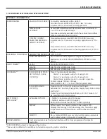
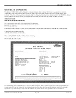


SYSTEM-10 BTU METER
ONICON Incorporated 727.447.6140
Page 12 onicon.com
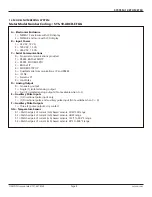
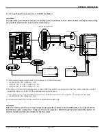
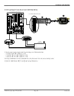
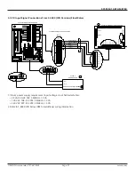
SECTION 3.0 INSTALLATION
The System-10 BTU Meter should be installed by experienced contractors with related knowledge and experience in
hydronic heating and cooling systems, and fluid metering applications in general. Contact ONICON for installation
assistance.
The installer should use good trade practices and must adhere to all state and local building or other applicable codes.
3.1 SITE SELECTION
3.1.1 The System-10 BTU Meter
3.1.2 The Flow Meter
Careful attention to the site selection for the system components will help the installers with the initial installation, reduce
start-up problems, and make future maintenance easier.
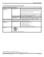
When selecting a site for mounting, consider the criteria under Section 1.6 WORKING ENVIRONMENT, as well as the
following.
IMPORTANT NOTE
Proper site selection is critical to the performance of this BTU meter. Both the flow meter and the two temperature
sensors must be properly located within the piping system in order to ensure an accurate energy measurement.
Find an easily accessible location where wire connections can be made and meter readings can be taken from floor
level. Mount the System-10 enclosure on a vibration free surface. Avoid locations such as the plenum of a fan coil, heat
exchanger or any housing that may contain electric motors or other strong sources of electrical interference.
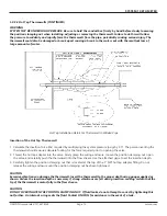
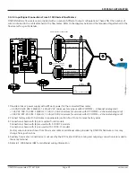
When properly installed, the flow meter will only measure flow associated with that portion of the piping system for which
the energy measurement is being made. The flow meter may be installed in either the supply or return line. Choose the
location with the longest straight run of unobstructed pipe. Please refer to 1.5 ADDITIONAL REQUIRED HARDWARE and to
the flow meter IOM for specific information regarding the straight run requirements.
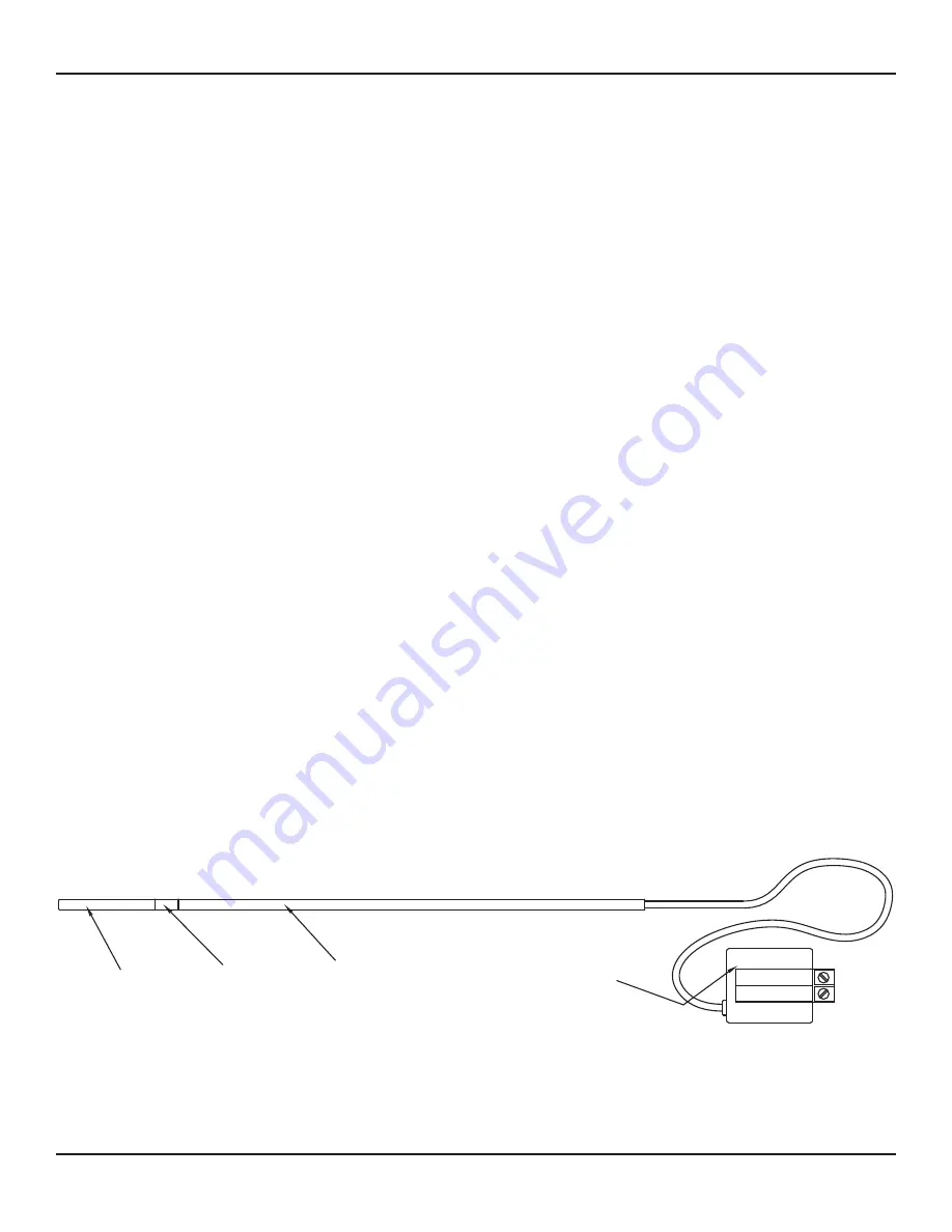
3.1.3 The Temperature Sensors
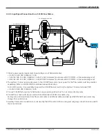
The two temperature sensors must be located in such a manner as to accurately measure only the temperature of the
supply line entering and the return line leaving the portion of the piping system for which the energy measurement is
being made.
If possible, find an easily accessible location where wire connections can be made from floor level. This will facilitate
any future service. Place the temperature sensors away from strong sources of electrical noise that might affect the
performance of the sensors.
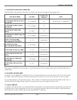
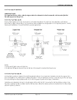
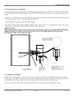
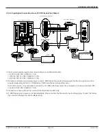
One temperature sensor thermowell will need to be placed in the same pipe with the flow meter. It should be located on
the downstream side of the flow meter. The downstream distance between the thermowell and flow meter should be at
least five pipe diameters, leaving enough clearance to remove either sensor from the pipe without interference from the
other sensor.
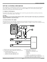
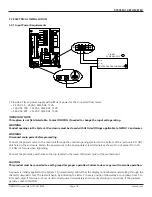
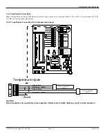
MODULE
ELECTRONICS
SLEEVE
(Length varies with
thermowell length)
SPACER
END PIECE
PLASTIC
SENSOR
TEMPERATURE
SIGNAL (RED)
REFERENCE (BLACK)
SUPPLY
S/N 123456


