


SYSTEM-10 BTU METER
ONICON Incorporated 727.447.6140
Page 13 onicon.com
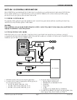
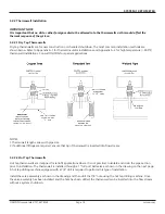
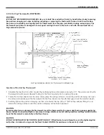
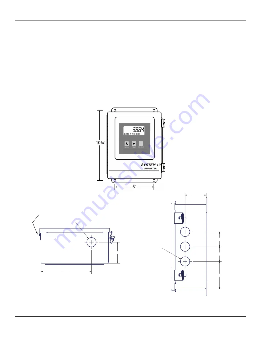
The mounting surface must be structurally sound and capable of withstanding a minimum weight of 40lbs (18kg). Use the
following screws for mounting.
(4) Machine screws - HHMS .25-20 x 1.5”
(4) Wood screws - FHLS .25 x 1.5”
(4) Concrete screws - HHCS .25 x 1.5”
2.500
1.750
1.750
3.250
3X 01.115
01.115
2.500
6.000
CONDUIT HOL LOCATION
BOTTOM VIEW
HINGE SIDE
SOWN FOR REFERENCE.
CONDUIT HOL LOCATION
RIGHT SIDE VIEW
CAUTION
DO NOT drill holes in the enclosure. Use only the openings that are provided.
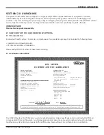
3.2.1 Transmitter Details and Dimensions
3.2 MECHANICAL INSTALLATION
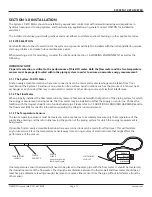
IMPORTANT NOTE
The components of the ONICON System-10 BTU Meter must be configured, programmed and installed together as a
system. Mixing components from different systems may result in significant measurement errors.


