


SYSTEM-10 BTU METER
ONICON Incorporated 727.447.6140
Page 15 onicon.com
WARNING
SYSTEM MAY BE UNDER HIGH PRESSURE. Be sure to hold the conduit box firmly by hand before slowly loosening
the position clamping nut when installing, adjusting or removing the thermowell. Failure to do this will allow
the pressure to suddenly and rapidly force the thermowell from the pipe, potentially causing serious injury. The
thermowell could also be damaged or break apart causing a break in the water seal with the resultant loss of
large amounts of water.
Insertion of the Hot Tap Thermowell
1.
Calculate the insertion force (lbs) required by multiplying the system pressure (psig) by 0.11. The person inserting the
thermowell should ensure adequate footing for the force required prior to opening the valve.
2. Thread the hot tap adapter into the valve. Firmly grasp the wiring enclosure, loosen the position clamping nut, open
the valve, and carefully push the thermowell into the flow stream. Use the attached gage to set the insertion depth.
3.
Carefully tighten the position clamping nut that is located at the top of the 1" NPT hot tap adapter fitting. Do not
release the wiring enclosure until the position clamping nut has been tightened.
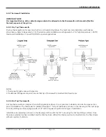
CAUTION
Excessive vibration can damage the thermowell. Insert the thermowell to the proper depth using gauge supplied as
shown. Reduce the insertion depth as necessary if strong vibrations are felt during insertion, making certain that the
tip of the thermowell remains fully in the flow stream.
CAUTION
DO NOT OVER TIGHTEN THE POSITION CLAMPING NUT. If fluid leaks, do not attempt to correct by tightening this
nut further. An internal o-ring seals the fluid. Contact ONICON for assistance in the event of a leak.
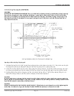
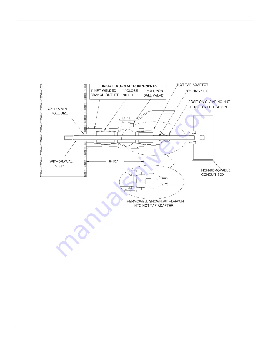
3.2.2.2 Hot Tap Thermowells (CONTINUED)
Hot Tap Installation Detail For Thermowell In Welded Pipe


