


SYSTEM-10 BTU METER
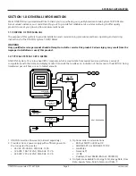
ONICON Incorporated 727.447.6140
Page 17 onicon.com
The temperature sensors are factory matched and tagged by serial number to a specific BTU meter. They are also labeled
as SUPPLY and RETURN temperature sensors. Please consult ONICON before attempting to use any other temperature
sensor.
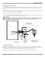
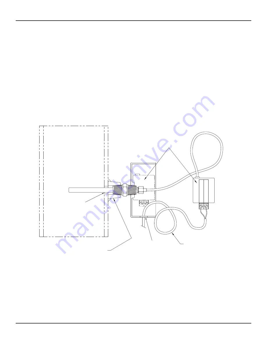
• Apply a thin coat of thermal compound to the temperature sensor, and gently insert the temperature sensor all the way
into the thermowell until it contacts the bottom of the cavity.
•
Gently tighten the retainer nut. DO NOT OVER TIGHTEN.
• The thermowell completely seals the plumbing system without the retainer nut. The only purpose for the nut is to keep
the sensor from losing contact with the bottom of the thermowell cavity.
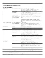
IMPORTANT NOTE
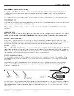
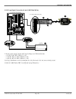
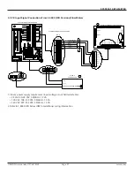
Cable length is specified at time of order. Cable provided for temperature sensors is #22 gauge twisted shielded pair.
Additional cable may be added in the field if necessary, but must be of twisted shielded pair construction.
(#22 gauge minimum and #18 gauge maximum)
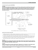
SIGNAL (RED)
REFERENCE
(BLACK)
SUPPLY
S/N 123456
5/8" MINIMUM
HOLE SIZE
1/2" HOLE FOR
CONDUIT OR
STRAIN RELIEF
FITTING.
PROVIDE 18-22 GA TWISTED
SHIELDED PAIR.
COIL ONE FOOT OF EXTRA
CABLE IN CONDUIT BOX.
1/2” NPT WELDED
BRANCH OUTLET
PLACE ELECTRONICS
MODULE IN BOX AFTER
CONNECTING WIRES.
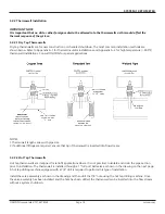
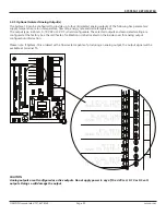
3.2.3 Temperature Sensor Installation
Determine which pipe (supply or return) has the longer unobstructed straight run. Install the flow meter in the longest
straight pipe run available. One temperature sensor can be installed five diameters downstream of the flow meter leaving
enough clearance to remove either sensor from the pipe without interference from the other sensor.
Refer to the flow meter IOM and/or other documentation that is provided with your ONICON flow meter.
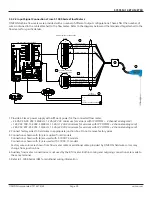
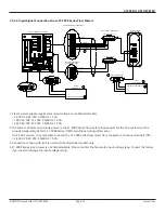
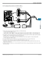
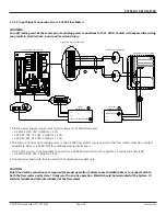
3.2.4 Flow Meter Installation


