


SYSTEM-10 BTU METER
ONICON Incorporated 727.447.6140
Page 18 onicon.com
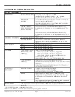
WARNING
Disconnect main power before proceeding.
CAUTION
This product must be connected to earth ground for proper operation. Failure to do so may result in erratic operation.
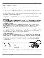
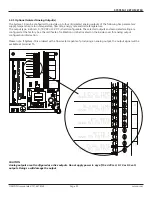
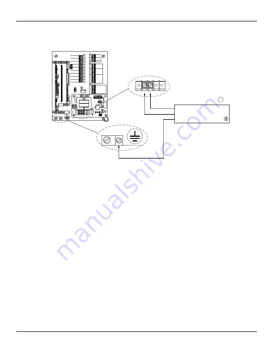
Connect the protective earth wire to the lug located in the lower left hand corner of the motherboard.
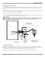
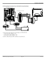
Connect the power source to the main unit through the conduit opening located on the bottom of the main unit. DO NOT
drill holes in the enclosure. Fasten the power wires to the appropriate screw terminals as shown. Do not exceed 12 in-lb
(1.4 Nm) of torque when tightening.
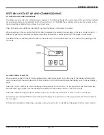
As power is initially applied to the System-10, immediately confirm that the display is illuminated and scrolling through the
character diagnostic test. The test will begin by indicating the letter P in every position followed by a countdown from 9 to
0 for each digit, If this does not occur, disconnect power immediately and re-verify all wiring connections. If the problem
persists, contact ONICON.
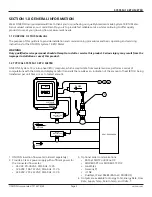
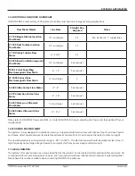
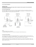
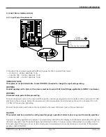
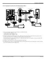
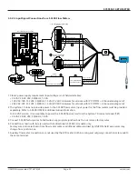
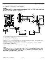
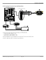
3.3 ELECTRICAL INSTALLATION
1.
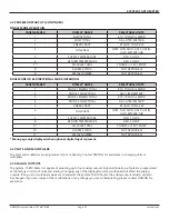
Provide a Class 2 power supply with sufficient power for the connected flow meter:
•
24 VAC: 20 - 28 VAC, 50/60 Hz, 12 VA
•
120 VAC: 108 - 132 VAC, 50/60 Hz, 15 VA
•
240 VAC: 207 - 253 VAC, 50/60 Hz, 15 VA
IMPORTANT NOTE:
This option is not field selectable. Contact ONICON if needed to change the input voltage rating.
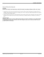
WARNING
Conduit openings in the System-10 enclosure must be closed with UL listed fittings applicable to NEMA 13 enclosures.
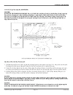
3.3.1 Input Power Requirements
J1
D5 C5
R3
R5
R1
C4
U2
C6
U1
C3
C1
D6
C2
5
G
60HZ
1
J2-1
+15
+24
J2-12
G
G
10
R7
H3
R1
LED1
T1
D1
D2
VAR1
F1
TB1
D4
D3
H1
1
SUPPLY
RETURN
SIGNAL
SHIELDS
REFERENCE
SIGNAL
REFERENCE
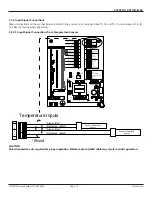
TEMPERATURE INPUTS
SHIELD
4-20mA +
4-20mA -
ALARM -
ALARM +
SUPPLY COMMON -
24 VDC
TOP TURBINE
DIRECTION -
FRE
FREQUENCY -
DIR
FLOW METER INPUTS
4-20mA +
SCALED -
AUXILIARY FLOW METER SIGNALS
ISOLATED ANALOG COMMON -
ANALOG COMMON -
0-10 VDC +
BOTTOM TURBINE
1
2
4
3
T1
2
1
3
4
5
MODE STATUS
MODE 2
MODE 1
1
7
6
8
10
11
9
13
14
15
16
18
17
12
-
+
+
-
+
BTU RATE
ANALOG OUTPUT
ANALOG OUTPUT
ANALOG OUTPUT
SUPPLY TEMP
RETURN TEMP
-
+
+
ALARM
-
OUTPUT
ANALOG OUTPUT
FLOW RATE
ANALOG OUTPUT
DELTA T
-
1
5
10
15
20
BTU METER OUTPUTS
BTU CONTACT OUTPUT
BTU CONTACT OUTPUT
-
+
INDICATOR
FLOW
15 V PULSE
RUN
TEST
60 HZ
S1
LED1
25
30
35
40
45
H2
5
13
11
7
6
5
8
10
12
4
2
T4
9
3
6
5
4
3
2
1
T5
T3
TB1
L1 (+)
POWER SUPPLY
1
N (-)
PROTECTIVE EARTH GROUND
PROVIDE A CLASS 2 POWER SUPPLY WITH SUFFICIENT POWER FOR THE
CLASS 2
L1
N
NOT USED
24 VOLTS


