


SYSTEM-10 BTU METER
ONICON Incorporated 727.447.6140
Page 20 onicon.com
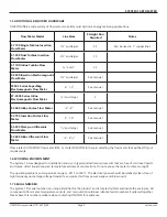
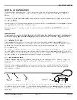
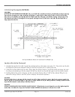
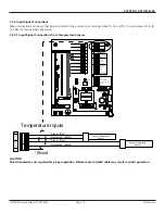
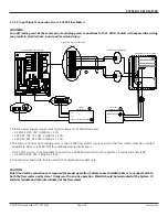
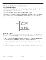
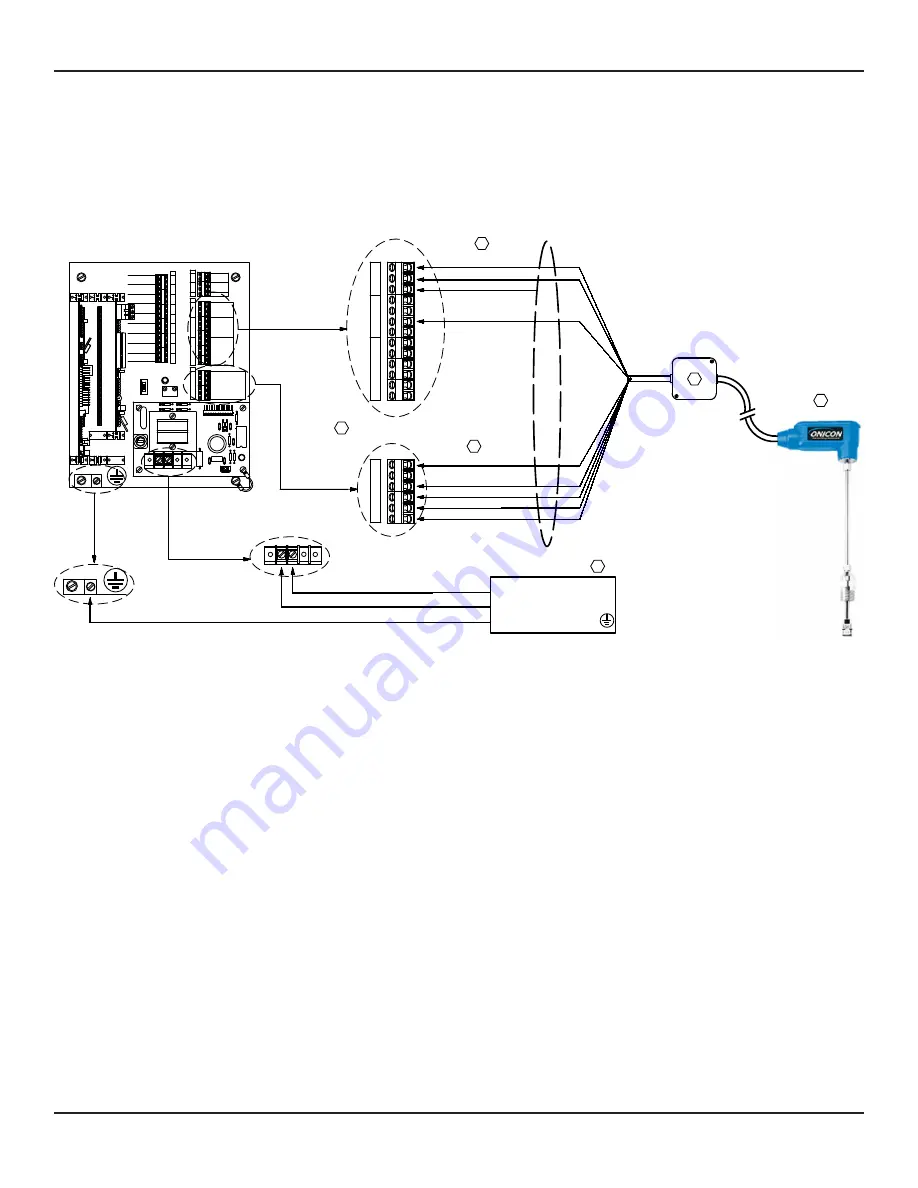
ONICON turbine flow meters are provided with a number of different output configurations. These affect the number of
wires contained in the cable attached to the flow meter. Refer to the diagram below and the laminated tag attached to the
flow meter for specific details.
3.3.2.2 Input Signal Connections From F-1000 Series Flow Meters
J1
D5 C5
R3
R5
R1 C4
U2
C6
U1
C3
C1
D6
C2
5
G
60HZ
1
J2-1
+15
+24
J2-12
G
G
10
R7
H3
R1
LED1
T1
D1
D2
VAR1
F1
TB1
D4
D3
H1
1
SUPPLY
RETURN
SIGNAL
SHIELDS
REFERENCE
SIGNAL
REFERENCE
TEMPERATURE INPUTS
SHIELD
4-20mA +
4-20mA -
ALARM -
ALARM +
SUPPLY COMMON -
24 VDC
TOP TURBINE
DIRECTION -
FRE
FREQUENCY -
DIR
FLOW METER INPUTS
4-20mA +
SCALED -
AUXILIARY FLOW METER SIGNALS
ISOLATED ANALOG COMMON -
ANALOG COMMON -
0-10 VDC +
BOTTOM TURBINE
1
2
4
3
T1
2
1
3
4
5
MODE STATUS
MODE 2
MODE 1
1
7
6
8
10
11
9
13
14
15
16
18
17
12
-
+
+
-
+
BTU RATE
ANALOG OUTPUT
ANALOG OUTPUT
ANALOG OUTPUT
SUPPLY TEMP
RETURN TEMP
-
+
+
ALARM
-
OUTPUT
ANALOG OUTPUT
FLOW RATE
ANALOG OUTPUT
DELTA T
-
1
5
10
15
20
BTU METER OUTPUTS
BTU CONTACT OUTPUT
BTU CONTACT OUTPUT
-
+
INDICATOR
FLOW
15 V PULSE
RUN
TEST
60 HZ
S1
LED1
25
30
35
40
45
H2
5
13
11
7
6
5
8
10
12
4
2
T4
9
3
6
5
4
3
2
1
T5
T3
3
9
2
4
12
10
8
5
6
7
11
13
1
SYS-10
T4
1
2
3
4
5
6
T5
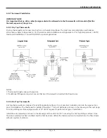
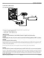
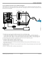
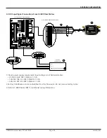
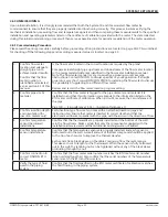
FLOW METER INPUTS CONNECTIONS
AUXILIARY FLOW METER
(A) RED (+) 24 VDC SUPPY
3
(A) BLACK (-) SUPPLY COMMON
(A) GREEN (+) FREQUENCY
(B OR C) BLUE (+) 4-20 mA
(A) WHITE (+) SCALED
(A) ORANGE (-) SCALED
SHIELD
(C) BROWN (-) ISO ANA COMMON
(B) BROWN (-) ANA COMMON
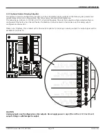
SYS-10 INTERNAL CIRCUIT BOARD
SIGNAL CONNECTIONS
TB1
L1 (+)
CLASS 2
TRANSFORMER
1
N (-)
PROTECTIVE EARTH GROUND
3
5
2
L1
N
NOT USED
24 VOLTS
4
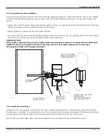
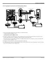
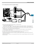
1.
Provide a Class 2 power supply with sufficient power for the connected flow meter:
•
24 VAC: 20-28 VAC, 50/60 Hz, 12 VA
(22 VAC minimum for versions with IP COMMS + 4 channel analog card)
•
120 VAC: 108-132 VAC, 50/60 Hz, 15 VA
(112 VAC minimum for versions with IP COMMS + 4 channel analog card)
•
240 VAC: 207-253 VAC, 50/60 Hz, 15 VA
(220 VAC minimum for versions with IP COMMS + 4 channel analog card)
2.
Connect factory wires to field wires in appropriate junction box. Do not remove factory wires.
3.
Connections shown with (A) are required for all models.
Connections shown with (B) are used with F-1XXX-10 models.
Connections shown with (C) are used with F-1XXX-11 models.
Factory wire colors are shown from flow meter cable or additional cable provided by ONICON, field wire colors may
change from junction box.
4.
Auxiliary flow meter connections are not used by the BTU meter. Both incoming and outgoing connections are made to
the same terminal.
5. Refer to F-1000 Series IOM for additional wiring information.


