


SYSTEM-10 BTU METER
ONICON Incorporated 727.447.6140
Page 28 onicon.com
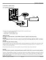
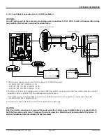
The System-10 is provided with a separate input for determining flow direction. Connections for this input are made at
T4 terminals 8 (+) and 9 (-). This input can be connected to a non-polarized contact closure relay or an open connector
output. Note that the input is polarized for sinking (NPN) open collector outputs. Totals will accumulate in the mode 1
registers whenever the contacts are closed.
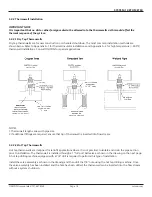
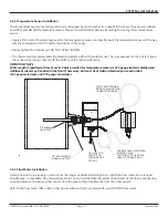
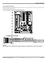
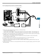
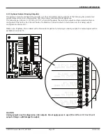
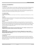
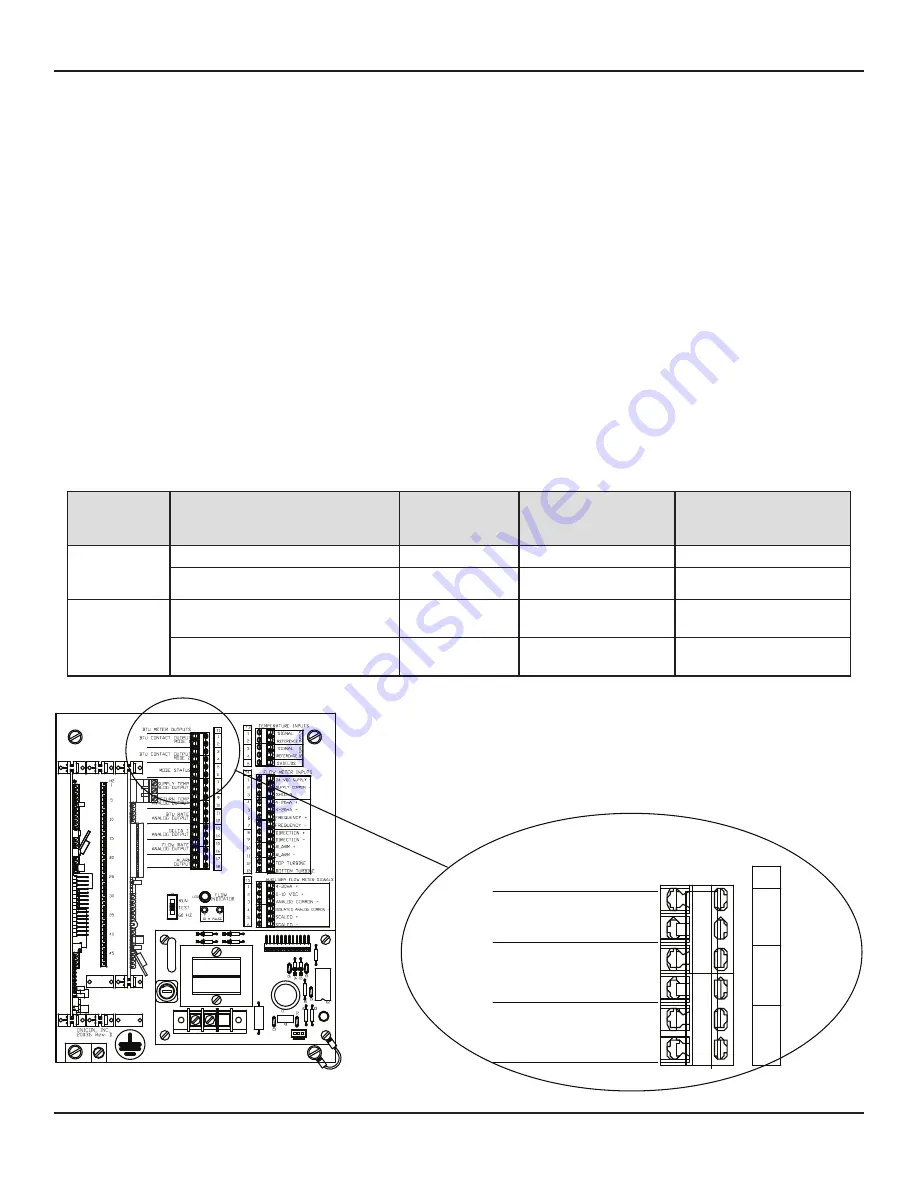
For single mode applications (heating or cooling), the output relay for energy total is located on the mother board at
T1, pins 1 and 2. The value of each “closure” is listed on the certificate of calibration and is the same as the energy total
multiplier displayed on the LCD (example: each closure = 10,000 BTU’s).
For dual mode applications (two-pipe heat/cool), the energy total for the heating mode (where supply temp is greater
than return temp) is provided at T1, pins 1 and 2. The energy total in the cooling mode is provided at T1, pins 3 and 4.
Mode status is at T1, pins 5 and 6 (open contact = mode 1 operation).
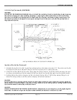
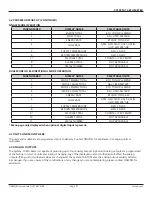
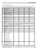
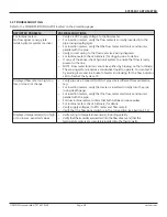
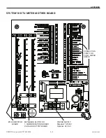
For bi-directional applications, the table below describes the relationship between mode 1 and mode 2 totals and forward
and reverse flow for ONICON insertion turbine and inline electromagnetic flow meters.
Do not exceed 4.5 in-lb (0.5 Nm) of torque when tightening the terminals.
3.3.4 Contact Closure Output For Energy Total(s) And Mode Status
3.3.3 Contact Closure Input For Flow Direction
FLOW
METER
MODEL
FLOW DIRECTION
RELATIVE TO
DIRECTION ARROW ON METER
FLOW METER
OUTPUT
CONDITION
System-10 MODE
STATUS INDICATOR
(T1 - PINS 5 & 6)
System-10 REGISTER
ACCUMULATING
TOTALS
F-3500-12
(Bi-directional
version)
Flow in the direction of arrow
Closed contact
Open contact
Mode 1
Flow reverse from direction arrow
Open contact
Closed contact
Mode 2
FT-3000 Series
Inline
Flow Meter
Flow toward (+) sign
Not energized
(open)
Closed contact
Mode 2
Flow toward (-) sign
Energized
(closed)
Open contact
Mode 1
J1
5
G
60HZ
1
J2-1
+15
+24
J2-12
G
G
10
R7
H3
R1
20075-50 REV. A
LED1
T1
D1
D2
VAR1
120VAC
F1
NEUTRAL
1/4 AMP
TB1
D4
D3
H1
1
BTU METER OUTPUTS
BTU CONTACT OUTPUT
MODE 1
BTU CONTACT OUTPUT
MODE 2
MODE STATUS
T1
1
2
3
4
5
6


