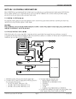


SYSTEM-10 BTU METER
ONICON Incorporated 727.447.6140
Page 3
onicon.com
TABLE OF CONTENTS
SECTION 1.0 GENERAL INFORMATION ................................................................................................................. 5
1.1 PURPOSE OF THIS MANUAL
......................................................................................................................................................5
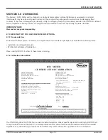
1.2 TYPICAL SYSTEM
-10 BTU METER .............................................................................................................................................5
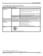
1.3 STANDARD FEATURES AND SPECIFICATIONS ..................................................................................................................6
1.4 MODEL NUMBERING SYSTEM
..................................................................................................................................................8
1.5 ADDITIONAL REQUIRED HARDWARE
...................................................................................................................................9
1.6 WORKING ENVIRONMENT
.........................................................................................................................................................9
1.7 SERIAL NUMBER
..............................................................................................................................................................................9
SECTION 2.0 UNPACKING ..................................................................................................................................... 10
2.1 CHECKING THAT YOU HAVE RECEIVED EVERYTHING
...............................................................................................10
2.1.1 Documentation ...................................................................................................................................................................10
2.1.2 Calibration Information ....................................................................................................................................................10
2.1.3 The System-10 BTU Meter ..............................................................................................................................................11
2.1.4 Temperature Sensors ........................................................................................................................................................11
2.1.5 Temperature Thermowells Installation Hardware
..................................................................................................11
2.1.6 Flow Meter ............................................................................................................................................................................11
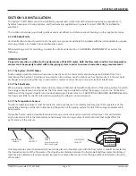
SECTION 3.0 INSTALLATION.................................................................................................................................. 12
3.1 SITE SELECTION
............................................................................................................................................................................12
3.1.1 The System-10 BTU Meter ..............................................................................................................................................12
3.1.2 The Flow Meter ....................................................................................................................................................................12
3.1.3 The Temperature Sensors ................................................................................................................................................12
3.2 MECHANICAL INSTALLATION
................................................................................................................................................13
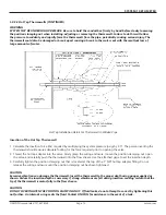
3.2.1 Transmitter Details and Dimensions ...........................................................................................................................13
3.2.2 Thermowell Installation ....................................................................................................................................................14
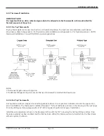
3.2.2.1 Dry Tap Thermowells ...........................................................................................................................................14
3.2.2.2 Hot Tap Thermowells
...........................................................................................................................................14
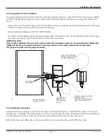
3.2.3 Temperature Sensor Installation ...................................................................................................................................17
3.2.4 Flow Meter Installation .....................................................................................................................................................17
3.3 ELECTRICAL INSTALLATION
....................................................................................................................................................18
3.3.1 Input Power Requirements .............................................................................................................................................18
3.3.2 Input Signal Connections ................................................................................................................................................19
3.3.2.1 Input Signal Connections from Temperature Sensors ...........................................................................19
3.3.2.2 Input Signal Connections From F-1000 Series Flow Meters ................................................................20
3.3.2.3 Input Signal Connections From F-2000 Series (Loop Powered Versions) Flow Meters
.............21
3.3.2.4 Input Signal Connections from FT-3000 Series Flow Meters ..............................................................22
3.3.2.5 Input Signal Connections from F-3500 Flow Meters ..............................................................................23
3.3.2.6 Input Signal Connections from FSM-3 Series Flow Meters ..................................................................24
3.3.2.7 Input Signal Connections from F-4300 Flow Meters ..............................................................................25
3.3.2.8 Input Signal Connections From F-4600 Flow Meters .............................................................................26
3.3.2.9 Input Signal Connections From F-4600 (LCD Versions) Flow Meters
...............................................27
3.3.3 Contact Closure Input For Flow Direction.................................................................................................................28
3.3.4 Contact Closure Output For Energy Total(s) And Mode Status
........................................................................28
3.3.5 Optional Isolated Analog Output(s)
............................................................................................................................29


