


SYSTEM-10 BTU METER
ONICON Incorporated 727.447.6140
Page 33 onicon.com
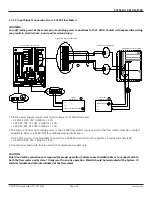
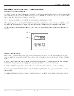
Upon initial installation, it is strongly recommended that both the System-10 and its associated flow meter be
commissioned to ensure that they are properly installed and functioning correctly. This process involves verifying the
mechanical installation, measuring flow and temperature signals and then comparing these measurements to the specified
installation and operating parameters listed on the certificate of calibration provided with the meter. The data collected
during this initial commissioning process will then serve as baseline data for periodic revalidation of the meter operation.
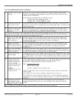
4.6.1 Commissioning Procedure
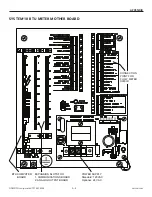
Please read the entire procedure carefully before proceeding. Wiring instructions are located on page 20-27. A worksheet
for checking off the following steps and recording measured values is located on page 35.
4.6 COMMISSIONING
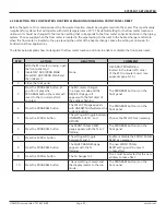
1.
Confirm flow meter
location and adequate
straight pipe run to
achieve desired results.
Confirm that the flow
meter location is
identified and selected
as per section 4.5 of this
manual.
Is the flow meter located in the correct location as required by the plans?
Compare actual straight pipe upstream and downstream of the flow meter location
to the recommended distances identified in the flow meter installation manual.
Note: The flow meter manual is very conservative, assuming worst-case pipe
obstructions. Contact ONICON to discuss specifics of your application. If straight
pipe run is very short, consult ONICON PRIOR to installing the flow meter to discuss
the possibility of upgrading to a different flow meter.
Review and record the flow meter location program setting.
2.
Confirm pipe size &
material.
Confirm that the flow meter is tagged for the pipe diameter and material it is
installed in and that this information corresponds to the information listed on the
BTU meter certificate of calibration. When in doubt, measure the circumference of
the pipe.
Pipe O.D. = (circumference / 3.14) – (insulation thickness x 2)
3.
Confirm insertion depth
and orientation (for
insertion meters only).
Each insertion type flow meter comes with an attached insertion gage and
instruction tag. Ensure that meter is inserted to correct depth and that the
electronics enclosure is parallel with the pipe, with the arrow in the direction of flow.
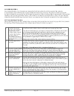
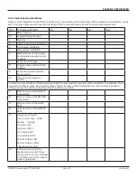
4.
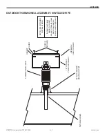
Confirm temperature
sensor thermowell
installations.
Confirm that the thermowells are properly installed and the bottom of the well
is in the flow stream. Make certain that only the components supplied with the
installation kit were used and that additional bushings were not added.
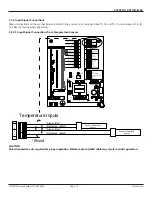
5.
Confirm temperature
sensor installations.
Confirm that the temperature sensors are properly installed, and each sensor is
bottomed out in the well. A small amount of thermal compound should be applied
to the tip of each sensor to improve the thermal transfer.
Each sensor has a black sleeve on the cable coming up from the metal sensor.
This sleeve in cut to length for the thermowell. When the sensor is fully bottomed
out in the well, the retaining nut can be tightened without any of the black sleeve
protruding through the nut.
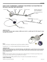
6.
Confirm connection to
correct ONICON BTU
meter.
Confirm that the flow meter serial number matches the BTU meter serial number
(when ordered together). Also confirm that the serial numbers of the temperature
sensors match the BTU and flow meters.
7.
Verify the type of fluid
used in the piping
system.
Confirm that the fluid specified on the BTU meter certificate of calibration matches
the fluid flowing in the piping system.


