


SYSTEM-10 BTU METER
ONICON Incorporated 727.447.6140
Page 35 onicon.com
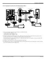
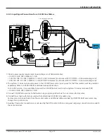
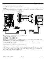
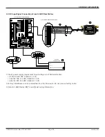
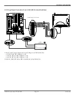
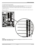
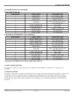
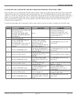
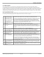
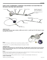
Please read all installation instructions carefully prior to proceeding with these steps. Wiring diagrams are located on page
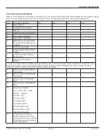
20-27. Use the following worksheet for checking off the commissioning steps and recording measured values:
STEP
TEST/MEASUREMENT
S/N:
S/N:
S/N:
S/N:
1.
Meter location
1a.
Supply/Return/Unknown
2.
Pipe size
3.
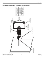
Insertion depth and orientation
4.
Thermowell installation
5.
Temperature installation
6.
Match BTU meter, flow meter
and temperature sensor serial
numbers.
7.
Verify the liquid type
8.
Supply voltage verified (Note
voltage.)
9.
Verify flow meter and temp
sensor wiring
10.
Flow test switch position
verified
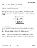
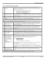
In order to proceed with the following steps, the BTU meter must be operating and connected to the network. There
must also be flow in pipes. Flow signal readings should be taken while holding the flow rate constant if possible.
Otherwise, take the various output readings as quickly as possible.
11.
Note and record the SUPPLY
temperature.
12.
Note and record the RETURN
temperature.
13.
Note and record the FLOW
RATE.
14.
Note and record the ENERGY
RATE.
15.
Frequency output(s):
Avg = green, Top = white
Bottom = orange
Avg Freq. (Hz):
Avg Freq. (VDC):
Top Turbine (Hz):
Top Turbine (VDC):
Bottom Turbine (Hz):
Bottom Turbine (VDC):
Calculated Flow Rate:
16.
Compare and record the
displayed values with those
shown on BTU meter certificate
of calibration and the network,
where appropriate.
4.6.2 Commissioning Worksheet


