


SYSTEM-10 BTU METER
ONICON Incorporated 727.447.6140
Page 36 onicon.com
The ONICON System-10 BTU Meter uses a microprocessor to calculate energy. Factory programmed settings provide rate
and total values in accordance with the customer’s application data. Refer to the BTU meter certificate of calibration for a
complete listing of factory settings. These settings may be reviewed and changed with assistance from ONICON.
The System-10 BTU Meter is also equipped with diagnostic indicator lights and self diagnostic test signals that confirm
the operation of the microprocessor and its input circuitry. Please contact ONICON if any of the diagnostic lights or test
signals listed below indicates a potential problem with the operation of the BTU meter.
5.1 DIAGNOSTICS
SECTION 5.0 DIAGNOSTICS
IMPORTANT NOTE
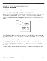
The second line of the display will alternate between TEST MODE and the normal display of engineering units and
multipliers whenever the flow test switch is in the TEST or 60 Hz positions.
IMPORTANT NOTE
After operating for five minutes in either the TEST or 60 Hz mode, the displayed flow and energy rate will be
disabled, and the meter will report a zero flow rate and a zero energy rate to the network. The meter will remain in
this state until the switch is set to RUN.
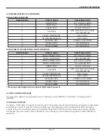
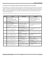
5.1.1 Diagnostic Lights
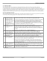
5.1.2 Flow Test Signals
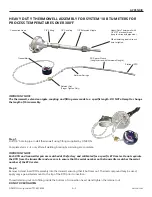
Flow Test
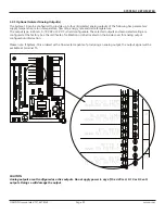
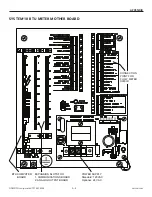
Located in the center of the motherboard immediately above the power supply board is a three position slide switch
used to test the flow input. When the switch is in the top position, the BTU meter input is connected to the flow meter.
When the switch is in the middle position, the BTU meter input is connected to two test terminals used to apply a variable
frequency to simulate flow. When the switch is in the bottom position, the BTU meter input is connected to a 50/60 Hz
signal that simulates a fixed flow rate. Refer to the BTU meter certificate of calibration to determine the correct display
reading when operating in the 50/60 Hz test mode.
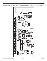
Low Voltage Power Supply
Located on the power supply board inside the System-10 BTU Meter is a single LEDs that will illuminate when +15 VDC is
present.
Liquid Flow
Located in the center of the motherboard next to terminal block T5, the LED will flash at a rate that is proportional to the
liquid flow rate for frequency flow signals. For 4 - 20 mA signals, the light will stay lit whenever the output is greater than 4
mA. An unlit LED indicates no flow signal.
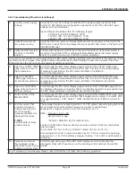
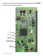
Temperature Test
As you are facing the component side of the BTU computer board, the temperature test push-button is along the top
edge of the board just to the left of the flat ribbon cable. It is labeled TEMP TEST. When pressed, a fixed voltage will be
applied to each temperature sensor input. Both the supply and return temperature menu pages will display a temperature
between 98°F to 102°F (36.6°C to 38.9°C). This test confirms the operation of the BTU computer board input circuitry for
temperature measurement.
5.1.3 Temperature Test Signals


