


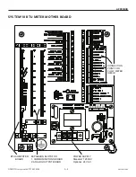
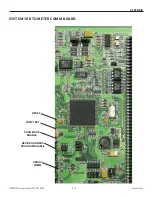

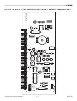
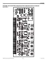

SYSTEM-10 BTU METER
ONICON Incorporated 727.447.6140
Page 37 onicon.com
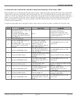
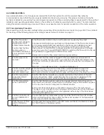
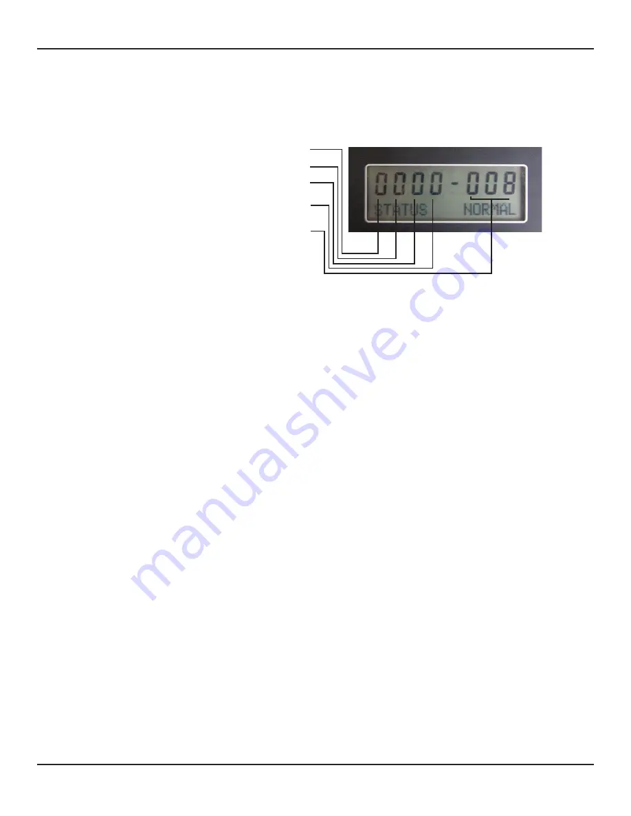
Alarm Status Menu Page -
STATUS NORMAL indicates normal operation.
The display will indicate STATUS ALARM when any one of the 5 alarms listed below is present
Volume (Flow) Scale Overrun
– This alarm is present whenever the volume flow rate causes the incremental volume total
to accumulate at a rate that is too fast.
To clear this alarm message, first confirm that the flow rate data and pipe diameter data on the tag attached to the meter
corresponds with the actual flow rate and actual pipe diameter. Any mismatch between the calibrated and actual flow
rates or the calibrated and actual pipe diameter will cause this alarm message to appear. Contact ONICON for assistance
in correcting this condition.
Heat (Energy) Scale Overrun
– This alarm is present whenever the energy flow rate causes the incremental energy total
to accumulate at a rate that is too fast.
To clear this alarm, first confirm that the actual temperature sensor readings and the actual flow reading are within
expected norms and match the calibration data provided for the System-10 BTU Meter. Either an excessively high delta
temperature or an unexpectedly high flow rate can cause this alarm message to appear. Contact ONICON for assistance in
correcting this condition.
Pulse Overrun
– This alarm is present whenever the incremental energy total is accumulating at a rate that exceeds the
time interval required for the 50% duty cycle of the pulse.
This alarm will normally coincide with either the volume scale or heat scale alarms. That message must be cleared before
this message can be cleared. Contact ONICON for assistance in correcting this condition.
Top Turbine
– This alarm will occur whenever zero pulses are accumulated from the top turbine while simultaneously
pulses are accumulating from the bottom turbine. To clear this alarm, the flow meter should be physically inspected to
determine why the top turbine is not rotating.
Bottom Turbine
– This alarm will occur whenever zero pulses are accumulated from the bottom turbine while
simultaneously pulses are accumulating from the top turbine. To clear this alarm, the flow meter should be physically
inspected to determine why the bottom turbine is not rotating.
System Reset Count
– The last 3 digits on the display indicate the total number of system resets that have occurred since
the current version of the firmware was loaded.
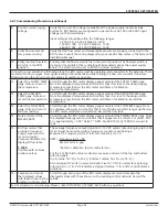
5.2 ALARM STATUS MENU PAGE
Volume (Flow) Scale Overrun: OK=0; Alarm=1
Heat (Energy) Scale Overrun OK=0; Alarm=1
Pulse Overrun: OK=0; Alarm=1
Top Turbine: OK=0; Alarm=1
Bottom Turbine: O
K=0; Alarm=2
System Reset Count: Number of system resets=0-255


