


SYSTEM-10 BTU METER
ONICON Incorporated 727.447.6140
Page 38 onicon.com
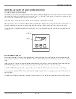
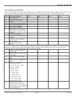
Refer to the COMMISSIONING GUIDE located on the preceding pages.
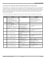
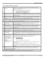
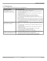
5.3 TROUBLESHOOTING
REPORTED PROBLEM
POSSIBLE SOLUTIONS
For turbine meters -
No flow signal / energy rate
(while hydronic system is active)
•
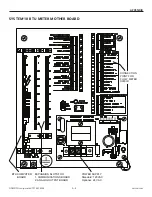
Verify 24 VDC supply voltage to the flow meter.
•
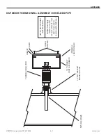
For insertion meters, verify the flow meter is correctly inserted into the
pipe (using depth gage).
•
For insertion meters, verify that the flow meter electronics enclosure is
parallel with the pipe.
•
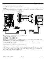
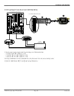
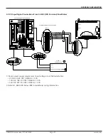
Verify correct wiring to the flow meter (see wiring diagram).
•
For turbine meters, check turbine(s) for clogging due to debris.
•
If none of the above, check hydronic system to ensure that flow is really
present in the line.
•
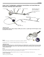
NOTE: Flow meter function cannot be verified by blowing on the turbine(s).
The sensing system requires a conductive liquid to operate. You can test it
by swirling it around in a bucket of water and looking for the flow indicator
LED to flash at the System-10.
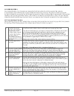
Displayed flow rate too high, too
low, or does not change
•
Verify pipe size. Contact ONICON if pipe size is different from calibration
tag.
• For insertion meters, verify that meter is inserted correctly into the pipe
(using depth gage).
•
For insertion meters, verify that the flow meter electronics enclosure is
parallel with the pipe.
•
For dual turbine meters, confirm that both turbines produce pulses.
•
For turbine meters, check turbine(s) for debris.
•
Verify supply voltages (to BTU meter and flow meter).
•
Verify that the flow signal switch is in the run position (see Section 5.1.2)
Displayed temperature(s) too high
or too low vs. expected values
•
Verify wiring to temperature sensor(s), including polarity.
•
Verify that thermowells are inserted into the flow stream and that the
temperature sensors are completely inserted into the thermowells.


