
SYSTEM-10 BTU METER
ONICON Incorporated 727.447.6140
Page 5
onicon.com
SECTION 1.0 GENERAL INFORMATION
1.1 PURPOSE OF THIS MANUAL
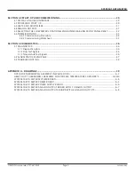
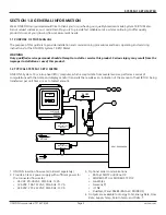
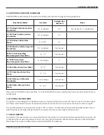
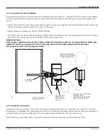
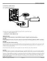
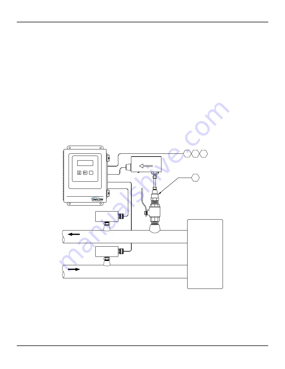
1.2 TYPICAL SYSTEM-10 BTU METER
We at ONICON Incorporated would like to thank you for purchasing our quality American made System-10 BTU Meter.
As our valued customer, our commitment to you is to provide fast reliable service, while continuing to offer quality
products to meet your growing flow measurement needs.
The purpose of this guide is to provide installation and commissioning procedures and basic operating and servicing
instructions for the ONICON System-10 BTU Meter.
ONICON’S System-10 is a true heat (BTU) computer, which accepts data from several sensors, performs a series of
computations with that data, and displays and/or transmits the results as an indication of the amount of heat (BTU’s) being
transferred per unit time or as a totalized amount.
WARNING
Only qualified service personnel should attempt to install or service this product. Serious injury may result from the
improper Installation or use of this product.
SYSTEM-10
SENSOR
TEMPERATURE
RETURN
TEMPERATURE
SUPPLY
SENSOR
HEAT EXCHANGER
RETURN
SCROLL
RESET
PROGRAM
BTU METER
3864
SUPPLY
FLOW
1
2
3
4
1.
ONICON insertion flow meter (ordered separately)
2.
Provide a Class 2 power supply with sufficient power for
the connected flow meter:
•
24 VAC: 20-28 VAC, 50/60 Hz, 12 VA
•
120 VAC: 108-132 VAC, 50/60 Hz, 15 VA
•
240 VAC: 207-253 VAC, 50/60 Hz, 15 VA
3. Optional serial communications:
•
BACnet MS/TP or BACnet IP
•
MODBUS RTU or MODBUS TCP/IP
•
LonWorks
• Siemens P1
• JCI N2
•
DualNet, IP and RS485 (BACnet/ MODBUS)
4. Outputs are available for Energy Total, Energy Rate, Flow
Rate, Supply Temp, Return Temp, and Delta-T.


