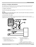
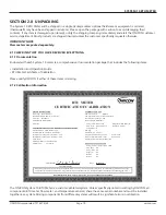


SYSTEM-10 BTU METER
ONICON Incorporated 727.447.6140
Page 7
onicon.com
SYSTEM-10 TRANSMITTER (CONTINUED)
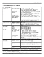
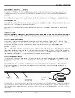
ELECTRICAL
CONNECTIONS
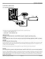
INPUT POWER
24 VAC input power: Use PVC jacketed copper cable with a wire
gauge suitable for the length of run and required maximum
current carrying capacity. The installation must comply with all
local, state and federal building codes.
120/240 VAC input power: Use a three (3) wire service with one
(1) wire a protective earth ground. The installation must comply
with all local, state and federal building codes.
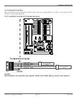
TEMPERATURE SIGNALS
Use 18-22 ga. twisted shielded pair
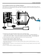
FLOW SIGNALS
Use 18-22 ga. shielded cable. See flow meter specification sheet
or flow meter IOM for the correct number of conductors.
TEMPERATURE SENSOR**
Solid state sensors are custom calibrated using NIST traceable temperature standard.
Current based signal (mA) is unaffected by wire length.
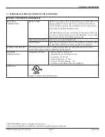
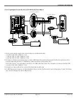
NETWORK
CONNECTIONS**
AVAILABLE OPTIONS
•
BACnet MS/TP or BACnet IP
•
MODBUS RTU or MODBUS TCP/IP
•
LonWorks - TP/FT-10F
•
Siemens Apogee - P1 FLN
• Johnson Controls Metasys - N2
•
DualNet, IP and RS485 (BACnet/ MODBUS)
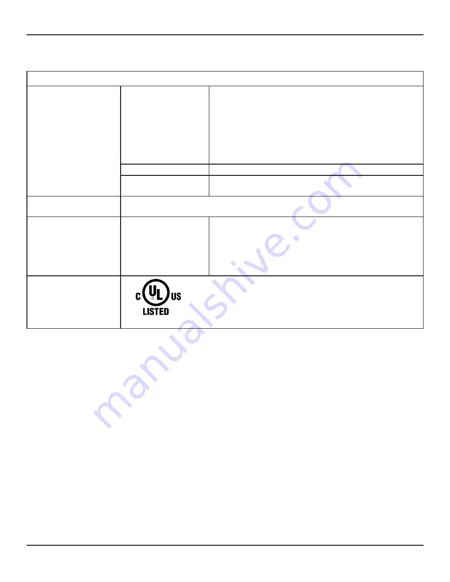
APPROVALS
NEMA 13 ENCLOSURE VERSION ONLY
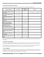
1.3 STANDARD FEATURES AND SPECIFICATIONS (CONTINUED)*
*
SPECIFICATIONS subject to change without notice.
**See model codification for additional information regarding option selections.


