


SYSTEM-10 BTU METER
ONICON Incorporated 727.447.6140
Page 8
onicon.com
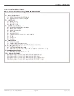
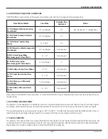
Meter Model Number Coding = SYS-10-ABCD-EFGG
A = Electronics Enclosure
1 = NEMA 13 enclosure with LCD display
2 = NEMA 4 enclosure with LCD display
B = Input Power
1 = 24 VAC, 12 VA
2 = 120 VAC, 15 VA
3 = 240 VAC, 15 VA
C = Serial Communications
0 = No serial communications provided
1 = RS485, BACnet MS/TP
2 = RS485, MODBUS RTU
3 = BACnet IP
4 = MODBUS TCP/IP
5 = DualNet serial communications, IP and RS485
6 = JCI N2
7 = Siemens P1
8 = LonWorks
D = Analog Output
0 = No analog output
1 = Single (1) isolated analog output
2 = Four (4) isolated analog outputs (Not available when C=5)
E = Auxiliary Pulse Inputs
0 = (1) Directional pulse input only
1 = (1) Directional pulse and auxiliary pulse input (Not availalbe when C = 0)
F = Auxiliary Pulse Outputs
1 = Three (3) pulse outputs, dry contact
GG = Temperature Sensor
01 = Matched pair of current (mA) based sensors, CHW/CW range
02 = Matched pair of current (mA) based sensors, HHW range
S1 = Matched pair of current (mA) based sensors, 122°F to 302°F range
S4 = Matched pair of current (mA) based sensors, 80°F to 400°F range
1.4 MODEL NUMBERING SYSTEM


