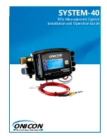
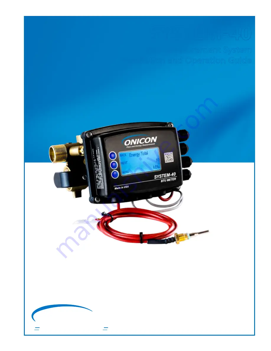
background image

 ON

I

CON

Flow and Energy Measurement

SYSTEM-40

BTU Measurement System

Installation and Operation Guide

Summary of Contents for SYS-40-010

Page 1: ...ONICON Flow and Energy Measurement SYSTEM 40 BTU Measurement System Installation and Operation Guide ...

Page 2: ...by the use of this product ONICON assumes no responsibility for any such harm owing to any defects in the product which were not predictable or for any indirect damages SAFETY PRECAUTIONS The following general safety precautions must be observed during all phases of installation operation service and repair of this product Failure to comply with these precautions or with specific WARNINGS given el...

Page 3: ...HAVE RECEIVED EVERYTHING 9 SECTION 3 0 INSTALLATION 10 3 1 SITE SELECTION 10 3 2 MECHANICAL INSTALLATION 11 3 3 INSTALLING THE FLOW SENSOR 12 3 3 1 Straight Run Requirements 12 3 3 2 Installing the Flow Meter 13 3 3 3 Installing Meter Couplings 14 3 3 4 Adjustment and Rotation 15 3 3 5 Orientation 16 3 4 INSTALLING THE TEMPERATURE SENSORS 17 3 4 1 Integral Mount Temperature Sensors Direct Insertio...

Page 4: ... 2 Units of Measure 25 4 2 2 3 Auxiliary Input Output Configuration Settings 26 4 3 USER SCREENS 28 4 3 1 Single Mode 28 4 3 2 Dual Mode 30 4 4 SEALING THE METER 30 SECTION 5 0 AUXILIARY INPUTS AND OUTPUTS 31 5 1 DETERMINING AUXILIARY INPUTS AND OUTPUTS CONFIGURATIONS 31 5 2 AUXILIARY INPUTS 31 5 3 AUXILIARY OUTPUTS 31 5 3 1 Single Mode Operation Pulse Outputs 31 5 3 2 Dual Mode Operation Pulse Ou...

Page 5: ... 1 BACNET OBJECT TYPES 40 7 2 PROTOCOL IMPLEMENTATION STATEMENT 40 7 3 DEVICE OBJECT 41 7 4 ANALOG INPUT S 42 7 5 ANALOG VALUES 43 7 6 BINARY VALUE S 44 7 7 MULTI STATE VALUE 45 7 8 TREND LOG MULTIPLE 46 SECTION 8 0 MODBUS 47 8 1 MODBUS MEMORY MAP 48 8 2 DIAGNOSTIC FUNCTION CODE 55 8 3 REPORT SLAVE ID FUNCTION CODE 57 ...

Page 6: ...2 TYPICAL SYSTEM 40 BTU METER INSTALLATION Return Supply Supply Return BTU METER SYSTEM 40 Made in USA BTU HR 49 50 BTU METER SYSTEM 40 Made in USA BTU HR 49 50 Fan Coil Unit or Air Handling Unit 2 1 Figure 1 Installation Detail for Pipe Size Range from 1 Figure 2 Installation Detail for Pipe Size Range from 1 2 3 Supply Temp 2 1 3 4 Fan Coil Unit or Air Handling Unit 1 Input Power 20 28V AC DC 5 ...

Page 7: ...SOLATED TOTALIZING PULSE INPUTS For use with devices providing sinking open collector or dry contact outputs Input Rating 30 VDC 10 mA maximum Pulse Duration 50 ms minimum ELECTRONICS ENCLOSURE IP65 polycarbonate with display WETTED COMPONENTS Lead free brass PEEK NETWORK CONNECTIONS Isolated RS485 serial interface AVAILABLE OPTIONS BACnet MS TP per ASHRAE Standard 135 1 2009 MODBUS RTU NETWORK CO...

Page 8: ...losure with Display D Input Power 0 24 V AC DC 1 Required for 2 meter NOT available on to 2 meters 2 Default configuration pulse inputs and outputs can be configured in the field 3 Valid for AAA meter size 050 011 Requires reducer bushing INSTL4002 TSI or INSTL4004 TSI 4 Valid for AAA meter size 050 011 Requires thermowell INSTL kit INSTL4001 TSD or INSTL4003 TSD 5 Valid for AAA 340 250 Requires t...

Page 9: ...al commercial and light industrial environments that are free of corrosive liquids and fumes temperature extremes and excess vibration It may be installed outdoors in protected spaces away from direct sunlight and rain sleet or snow The operating ambient air temperature range is 13 F to 131 F Electrical power should be clean free of excess high frequency noise and large voltage transients The seri...

Page 10: ... with the initial installation reduce start up problems and make future maintenance easier When selecting a site for mounting the system components consider the criteria under Section 1 6 WORKING ENVIRONMENT as well as the following limitations that apply to the installation of the meter The flow sensor body must be correctly oriented with respect to the direction of flow in the pipe Meters instal...

Page 11: ...0 1 high flow 15 00 10 23 5 75 4 50 L Total 1 METER DIMENSIONS BTU METER SYSTEM 40 Made in USA BTU HR 49 50 BTU METER SYSTEM 40 Made in USA BTU HR 49 50 W L H Size L Total L W H 1 15 25 10 20 5 75 4 50 1 17 00 11 80 6 25 5 00 2 17 60 11 80 6 50 5 50 2 11 81 10 23 L Total 1 2 METER DIMENSIONS 8 75 7 00 BTU METER SYSTEM 40 Made in USA BTU HR 49 50 BTU METER SYSTEM 40 Made in USA BTU HR 49 50 2 meter...

Page 12: ...obstructed pipe requirements vary considerably based on the nature of the upstream obstructions ONICON always recommends that the sensor be located with as much straight pipe upstream as possible 3 3 INSTALLING THE FLOW SENSOR 3 3 1 Straight Run Requirements Upstream Obstruction Minimum Upstream Straight Run Required Pipe Diameters Meter Size 1 1 2 Single Elbow 0 0 Expander Reducer 0 0 Coil Upstre...

Page 13: ...Do not install the sensor downstream of modulating valves or partially open valves Fully open isolation valves e g ball valves are acceptable E Do not install the sensor at the inlet of a pump To prevent cavitation the minimum operating pressure at the inlet of the meter must always exceed the pressure drop across the sensor F Avoid installing the sensor downstream of multiple bends out of plane w...

Page 14: ... Place a corresponding mark on the coupling nut of degrees based on table on the following page counter clockwise Hold meter body while rotating coupling nut clockwise until marks line up DO NOT over tighten Repeat process on opposite side of flow meter body NOTE Torque setting is not an accurate means of gaging compression on gasket due to the lack of resilience in the gasket material Pressurize ...

Page 15: ...ing in any orientation IMPORTANT NOTE When installing the meter in a vertical pipe with upward flow you must rotate the enclosure back plate 180 when rotating the display 90 To accomplish this temporarily remove the four cover screws and rotate the backing plate Sensor mounting bracket Slide enclosure off of sensor mounting bracket Retaining Screw Retaining Screw Mounting tracks Model Meter Size M...

Page 16: ...cations where the pipe may not be completely full Orient the 1 2 meters as shown below The meter may be installed with upward or downward flow in vertical pipes in closed loop pressurized systems Avoid any installation locations where the pipe may not be completely full The flow sensor is installed with threaded meter couplings and flat sealing gaskets as shown below Orient the sensor body by alig...

Page 17: ...r The tapered sensors are provided with an M10 threaded fitting and a flat sealing gasket For standard installations an M10 x NPT or flush bushing is provided for use with a customer supplied line size tee The torque required to properly install the temperature sensors is 4 lb ft 3 4 INSTALLING THE TEMPERATURE SENSORS BTU METER SYSTEM 40 Made in USA BTU HR 49 50 1 2 3 4 5 6 7 8 CAUTION The platinu...

Page 18: ...8 Customer supplied line size tee BTU METER SYSTEM 40 Made in USA BTU HR 49 50 1 2 3 4 5 6 7 8 3 4 2 Remote Mount Temperature Sensors Direct Insertion Style 1 2 1 System 40 BTU Meters configured with direct insertion style provided with two threaded thermowells or copper sweat thermowells for use with customer supplied line size tees CAUTION The platinum RTD sensors provided with the System 40 are...

Page 19: ...pe 2 Supply pipe 3 Remote temperature sensor installation kit 4 Fan coil unit or air handling unit 5 RTD temperature sensor provided by ONICON 6 Thermowell provided by ONICON 7 1 solder x 1 2 NPT bushing OR line size x 1 2 bushing Provided by customer or ordered from ONICON 8 Customer supplied line size tee 5 6 7 8 BTU METER SYSTEM 40 Made in USA BTU HR 49 50 3 1 2 4 CAUTION The platinum RTD senso...

Page 20: ... has two mounting holes designed for 10 screws The remote mounting bracket also has parallel slots that allow for the use of pipe clamps when mounting the enclosure on a stanchion or pipe The bracket may be used as a template for marking hole locations Also shown is the back of the enclosure The mounting bracket slides onto tracks on this back plate 3 5 REMOTE MOUNTING THE ENCLOSURE Slot for Pipe ...

Page 21: ...ERIAL TB3 TB2 H3 TB8 TB7 TB6 TB5 SW6 SW7 SW2 SW1 C34 C33 R6 DS3 R8 H2 SERIAL 2 1 GRD DS2 R60 3 JMP5 1 CAUTION INSTALL SIDE UP CR2032 BATTERY BAT1 Supply Internal RTD Return External RTD TB1 TB4 4 3 2 1 4 3 2 1 1 2 3 4 5 6 7 8 1 2 3 1 2 1 2 1 2 1 2 1 24V AC DC 2 24V Common 3 AUX I O 1 4 AUX I O 1 5 AUX I O 2 6 AUX I O 2 7 AUX I O 3 8 AUX I O 3 Microprocessor reset push button JP1 J11 2 1 2 1 2 1 J1...

Page 22: ...ns and the meter is functional Sec 6 0 When power is first applied to the meter the display will be illuminated and the following start screen will appear Use the three pushbuttons on the left side of the display to navigate the display pages and change settings Pressing NEXT then SEL select will allow you to navigate the Main Menu display The System 40 BTU Meter is pre programmed based on the spe...

Page 23: ... 127 Default 017 Press EDIT then MORE to select digits To continue press SAVE and then NEXT BACnet device instance range 0 4 194 302 Default 0057017 Press EDIT then MORE to select digits To continue press SAVE and then NEXT Baud rate for the BACnet communications Options included 9600 19200 38400 or 76800 Default 38400 Press EDIT then MORE to select digits To continue press SAVE and then NEXT BACn...

Page 24: ...NEXT Error checking parity for the MODBUS communications Options include None Odd or Even Default None Press EDIT then MORE to select parity To continue press SAVE and then NEXT Stop bits options include 1 or 2 Default 1 Press EDIT then MORE to select digit To continue press SAVE and then NEXT Modbus Address 0 247 NEXT 017 EXIT EDIT Baud Rate NEXT 9600 EXIT EDIT Parity Odd Even None NEXT None EXIT...

Page 25: ...y To continue press SAVE and then NEXT Use this menu option to continue commissioning or return to normal operation Press NEXT to continue the meter set or press SAVE to complete the installation 4 2 1 3 Additional Displays Additional displays can be configured after selecting the communication Meter Location NEXT Supply EXIT EDIT Set Time NEXT HH MM SS EXIT EDIT Set Date NEXT YYYY MM DD EXIT EDIT...

Page 26: ...ge This display only appears when Propylene Glycol or Ethylene Glycol selected above The percentage range is from 0 50 To continue press SAVE and then NEXT Press EDIT then MORE to select metric or IP flow rate unit To continue press SAVE and then NEXT Press EDIT then MORE to select metric or IP volume unit To continue press SAVE and then NEXT Press EDIT then MORE to select metric or IP energy unit...

Page 27: ... EDIT Counts Pulsed Output 3 NEXT EXIT EDIT Select Type Set Meter Press NEXT edit units of measure SAVE completes install with current settings NEXT BACK SAVE The default auxiliary configuration set as 2 IN 1 OUT This can be changed by select EDIT and then MORE To continue press SAVE and then NEXT Press EDIT then MORE to select the number of aux input To continue press SAVE and then NEXT Press EDI...

Page 28: ...select number of aux input To continue press SAVE and then NEXT Press EDIT then MORE to define aux input 1 To continue press SAVE and then NEXT Press EDIT then MORE to select type of pulse output 2 Options include Energy Mode Volume Mode Alarm and Modbus Coil See 5 3 AUXILIARY OUTPUTS for more details To continue press SAVE and then NEXT Press EDIT then MORE to select analog signal as 4 20 mA 0 5 ...

Page 29: ...MENU to get to the troubleshooting menu See section 6 0 TROUBLESHOOTING for more details on the alarm messages and their solutions 4 3 1 Single Mode Single mode is the energy calculation in either the heating or cooling mode It is chosen through commissioning the meter See 4 2 2 1 METER CONFIGURATION SETTINGS for more details on how to select the mode status Below are the default setup screens for...

Page 30: ...urs the meter has run These screens will only appear if Aux I O was configured at factory for Pulse Input See section 5 0 AUXILIARY INPUTS and OUTPUTS for more information Important Note When reviewing the Supply and Return temperature display pages note which one has the word FLOW in the lower left corner of the page This is an indication of the flow sensor location in the piping system Verify th...

Page 31: ...ter See 4 2 2 1 METER CONFIGURATION SETTINGS for more details on how to select the mode status Similar to the Single Mode when Dual Mode selected Energy Total and Volume Total will be displayed for M1 and M2 cooling and heating mode An extra Mode Status screen will be displayed for the mode indication 4 4 SEALING THE METER Once commissioning is complete install the two security seals provided with...

Page 32: ...splay The value transmitted over the RS485 network will be a unitless count regardless of the description programmed into the System 40 To reset the auxiliary pulse input counts please refer to the registers in the MODBUS memory maps located in section 8 0 MODBUS When configured for auxiliary pulse outputs the System 40 will have the ability to provide contact closure pulses for use with a remote ...

Page 33: ...l require 10 LCD display accumulations before a pulse output is provided A pulse will occur when the Mode 2 volume is incremented Mode 2 is cooling mode supply temp return temp Mode 1 Total Energy Units match LCD totalizer Output can be scaled for 1 10 or 100 Example If configured for 10 the meter will require 10 LCD display accumulations before a pulse output is provided A pulse will occur when t...

Page 34: ...o the analog output The analog output is configured in the commissioning menu See 4 2 2 3 AUXILIARY INPUT OUTPUT CONFIGURATION SETTINGS for more information The minimum value set in programming will be what 4 mA or 0 V is equivalent to The maximum value set in programming will be what 20 mA 5 V 10 V is equivalent to Example A 4 20 mA analog output configured as supply temperature with a minimum of...

Page 35: ...B1 Pulse Input Pulse Output Terminal Block TB1 Terminal Block TB1 Terminal Block TB1 Jumper Location J11 5 5 JUMPER LOCATIONS AND DETAILS The ONICON System 40 can be ordered pre configured with the required auxiliary inputs outputs or an analog output already selected The meter has several options that can be selected by installing or removing jumpers If the outputs need to be changed move the jum...

Page 36: ...n System Fault This message indicates a hardware malfunction At this point meter will not calculate the energy Contact ONICON technical support for further assistance Reverse Flow This message occurs when meter detects reverse water flow At this point meter will not calculate the energy Verify the flow direction The flow direction should follow the arrow indicator in the meter body Otherwise conta...

Page 37: ...ture sensor cables do not contact each other Otherwise contact ONICON technical support for further assistance Low Flow This message occurs when the flow reading is below the minimum flow threshold of the meter e g 0 03 gpm for meter The meter will not calculate energy in this state Contact ONICON technical support for further assistance High Flow This message occurs when the flow reading is above...

Page 38: ...gnal 10 49 Poor transducer signal Reading 10 Transducer signal is not functioning Speed of Sound is desirable to record the initial value at a defined temperature during commissioning Transit Time measure the difference in time from when a signal is transmitted from one transducer until it crosses the pipe and is received by the other transducer The greater the difference the faster the liquid is ...

Page 39: ...ro at 12 01 AM on January 1st of each year Prev Yr Energy provides the energy total measured from the previous year This total will be replaced by the YTD Energy total at 12 01 AM on January 1st of each year Prev Yr Volume provides the flow total measure from the previous year This total will be replaced by the YTD Volume total at 12 01 AM on January 1st of each year User Energy Total is a totaliz...

Page 40: ...rovides a read only date of calibration for the meter Versions provides a read only current versions of the meter Config Number provides a read only number gives the complete the configuration values of the meter Serial Number 000000 NEXT EXIT MENU Manufacture Date 0000 00 00 NEXT EXIT MENU Year Month Day Calibration Date 0000 00 00 NEXT EXIT MENU Year Month Day Versions App 0 0 0 Boot 0 0 0 DA 0 ...

Page 41: ... master Clause 9 baud rate s 9600 19200 38400 76800 Device Address Binding No BBMD support registration by Foreign Devices No Character Set Supported ANSI X3 4 BACnet Interoperability Building Blocks Supported Annex K Data Sharing ReadProperty B DS RP B Data Sharing ReadProperty Multiple B DS RPM B Data Sharing WriteProperty B DS WP B Data Sharing WriteProperty Multiple B DS WPM B Device Managemen...

Page 42: ...s Supported Read property Read property multiple Write property Write property multiple Read range Who has I have Who is I am Device communications control Time synchronization UTC time synchronization Read only Object Types Supported Analog input Analog value Binary input Device Multi state value Trend log multiple Read only Object List Device 57017 analog input 1 10 analog value 1 24 binary valu...

Page 43: ...resent Value 1000000000 Read only Max Present Value 1000000000 Read only Resolution 0 000001 Read only Object Identifier Function Analog input 1 Energy rate Analog input 2 Volume rate Analog input 3 Supply temperature Analog input 4 Return temperature Analog input 5 Delta temperature Analog input 6 Signal strength Analog input 7 Signal quality Analog input 8 Speed of sound Analog input 9 Peak ener...

Page 44: ...tal Previous Year mode 2 energy total Analog value 7 User defined energy total User mode 1 energy total Analog value 8 User defined energy total User mode 2 energy total Analog value 9 Volume total Mode 1 volume total Analog value 10 Volume total Mode 2 volume total Analog value 11 Y T D volume total Y T D mode 1 volume total Analog value 12 Y T D volume total Y T D mode 2 volume total Analog valu...

Page 45: ...e FALSE Writable Elapsed Active Time Various Read only Priority Array NULL NULL NULL NULL NULL NULL NULL NULL NULL NULL NULL NULL NULL NULL NULL NULL Read only Relinquish Default 0 Read only Binary Value Objects Object Identifier Description Notes Binary value 1 Mode indication 0 mode 1 1 mode 2 Binary value 2 Location 0 supply 1 return Binary value 3 User defined energy total reset Mode 1 1 reset...

Page 46: ... of Service FALSE Writable Number of States 11 Read only State Text Normal Low Supply Temperature High Supply Temperature Low Return Temperature Delta T Minimum High Energy Rate Low Signal Quality Comm Error Low Supply Voltage System Fault Read only Relinquish Default 0 Read only Multi state Object Object Identifier Description Notes Multi state value 1 Reports the operating status of the meter Nu...

Page 47: ... Type POLLED Read only Log Interval 90000 Writable Stop When Full FALSE Read only Buffer Size 480 Read only Log Buffer Read only Record Count 0 Writable Total Record Count 0 Read only Trend log Multiple Object Object Identifier Description Notes Trendlog Multiple 1 Logs the following BACnet objects Peak energy rate Average delta temp Incremental energy total mode 1 Incremental energy total mode 2 ...

Page 48: ... per hour x 1 000 kBtu hr Btu x 1 000 kBtu Tons Tons Btu x 1 000 000 MBtu Watts x 1 000 kW Ton hour TonHr Watts x 1 000 x 1 000 000 MW Joules x 1 000 000 MJ Volume Rate Flow Watt hours x 1 000 kWHr Gallons per minute GPM Volume Total Liters per second L s Gallons Gal Cubic feet per minute ft3 min Liters Liters Cubic meters per hour m3 hr Cubic Feet ft3 Temperature Cubic Meters m3 Degrees Fahrenhei...

Page 49: ... 0 once reset is complete 11 Aux Output 1 Coil NA NA Read Write Turn coil ON 1 to latch Aux I O 1 closed Turn coil to OFF 0 to latch I O 1 open Aux I O 1 must have been configured as an output at the factory and programmed for MODBUS Coil in the commissioning menu 12 Aux Output 2 Coil NA NA Read Write Turn coil ON 1 to latch Aux I O 2 closed Turn coil to OFF 0 to latch I O 2 open Aux I O 2 must ha...

Page 50: ...perature C Input Register Floating Point Register 1 of 2 30028 Delta Temperature C Input Register Floating Point Register 2 of 2 30029 Signal Strength No Units Input Register Floating Point Register 1 of 2 Range 1 31 1 is highest signal strength 31 is lowest signal strength 30030 Signal Strength No Units Input Register Floating Point Register 2 of 2 Range 1 31 1 is highest signal strength 31 is lo...

Page 51: ... 1 of 2 30072 Year to Date Energy Total Single Mode TonHr Input Register Floating Point Register 2 of 2 30073 Year to Date Energy Total Single Mode MJ Input Register Floating Point Register 1 of 2 30074 Year to Date Energy Total Single Mode MJ Input Register Floating Point Register 2 of 2 30075 Year to Date Energy Total Single Mode kWHr Input Register Floating Point Register 1 of 2 30076 Year to D...

Page 52: ... Input Register Floating Point Register 2 of 2 30119 Previous Year Energy Total Mode 2 MBtu Input Register Floating Point Register 1 of 2 30120 Previous Year Energy Total Mode 2 MBtu Input Register Floating Point Register 2 of 2 30121 Previous Year Energy Total Mode 2 TonHr Input Register Floating Point Register 1 of 2 30122 Previous Year Energy Total Mode 2 TonHr Input Register Floating Point Reg...

Page 53: ...me Total Mode 1 Gal Input Register Floating Point Register 2 of 2 30167 Volume Total Mode 1 Liters Input Register Floating Point Register 1 of 2 30168 Volume Total Mode 1 Liters Input Register Floating Point Register 2 of 2 30169 Volume Total Mode 1 ft3 Input Register Floating Point Register 1 of 2 30170 Volume Total Mode 1 ft3 Input Register Floating Point Register 2 of 2 30171 Volume Total Mode ...

Page 54: ...ster Floating Point Register 2 of 2 30215 Previous Year Volume Total Mode 1 Liters Input Register Floating Point Register 1 of 2 30216 Previous Year Volume Total Mode 1 Liters Input Register Floating Point Register 2 of 2 30217 Previous Year Volume Total Mode 1 ft3 Input Register Floating Point Register 1 of 2 30218 Previous Year Volume Total Mode 1 ft3 Input Register Floating Point Register 2 of ...

Page 55: ...y Pulse Input Count Input 1 Input Register Floating Point Register 1 of 2 Unitless count Value is representative of the total number of pulses received on input 30254 Auxiliary Pulse Input Count Input 1 Input Register Floating Point Register 2 of 2 Unitless count Value is representative of the total number of pulses received on input 30255 Auxiliary Pulse Input Count Input 2 Input Register Floatin...

Page 56: ...The entire response message should be identical to the request 01 Restart Communications Option The System 40 serial line port will be initialized and restarted and all of its communications event counters are cleared If the port is currently in Listen Only Mode no response is returned This function is the only one that brings the port out of Listen Only Mode If the port is not currently in Listen...

Page 57: ...ast restart restart communications option or power up This count is also available in the System 40 s diagnostic menu page 15 0F Hex Return Server No Response Count The response data field returns the quantity of messages addressed to the System 40 for which it has returned no response neither a normal response nor an exception response since its last restart restart communications option or power...

Page 58: ...e ID When a message is sent to the System 40 requesting to report the slave ID the following information is returned System 40 XXXXXX where XXXXXX serial number of the System 40 The System 40 will report data in decimal or HEX depending on the control system settings The data must be converted from decimal HEX to ASCII in order to form the string 8 3 REPORT SLAVE ID FUNCTION CODE ...

Page 59: ...451 Belcher Road South Largo FL 33773 USA Tel 1 727 447 6140 Fax 1 727 442 5699 www onicon com sales onicon com SYSTEM 40 BTU MEASUREMENT SYSTEM October 2019 DOC 0001007 ONICON Flow and Energy Measurement ...

Reviews: