background image

6

For safety reasons, do not turn on any devices or components
until you have completed all wiring procedures.

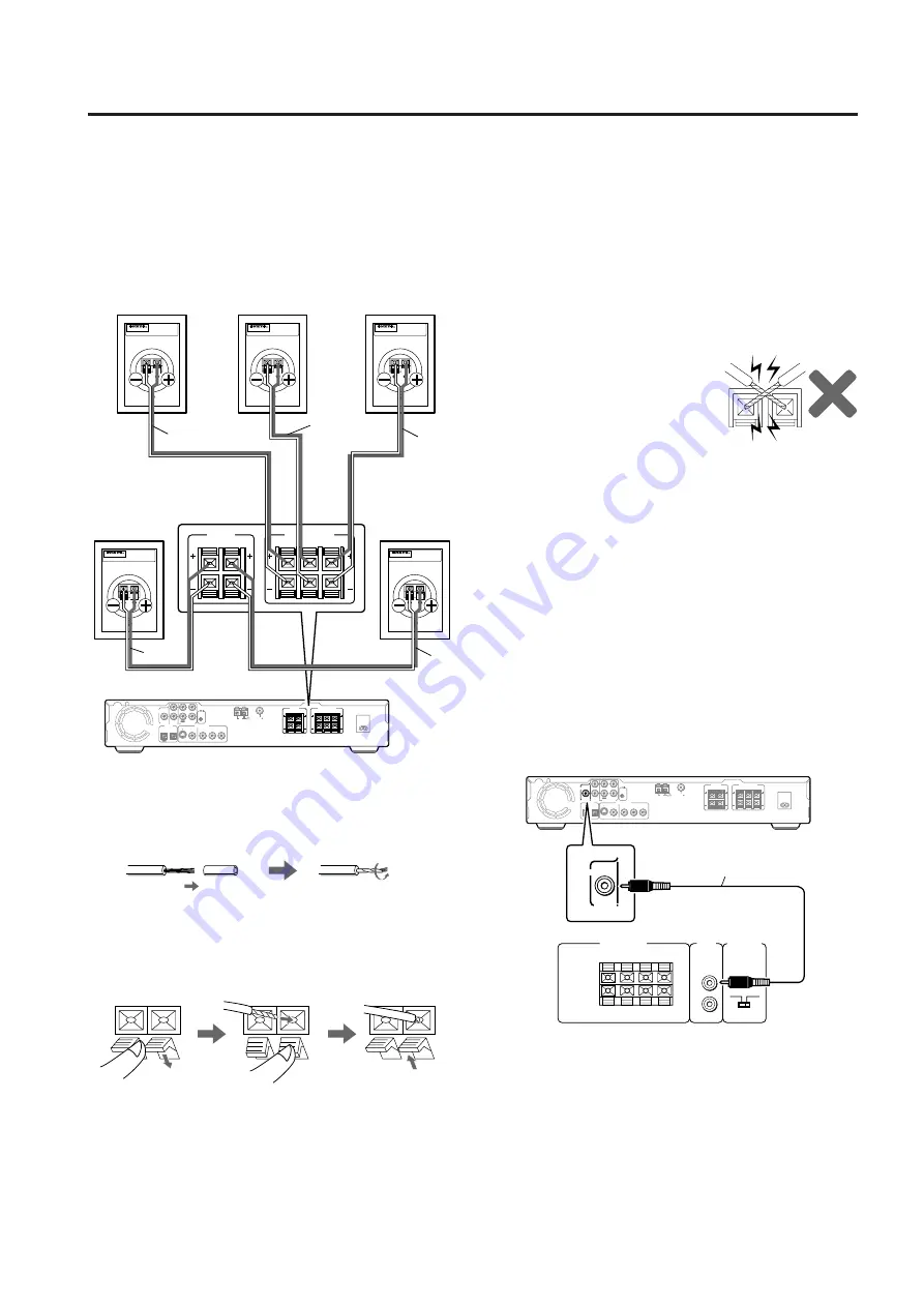
Connecting the satellite speakers

Note:
The nominal impedance of this speaker system is 6 

. Use

only amplifiers capable of handling this impedance.

Connecting the speakers

R

SPEAKER LEVEL

INPUT

FROM

AMP/RECEIVER

AUTO STANDBY

LINE

INPUT

L

R

OFF

ON

OUTPUT

TO SPEAKERS

(MONO)

+

_

L

+

_

R

+

_

L

+

_

AC INLET

DIGITAL

OPTICAL

VIDEO OUTPUT

AM

FM 75

S VIDEO

VIDEO

COMPONENT

ANTENNA

IN

Y

PB

PR

OUT

ANTENNA

PREOUT

SUB

WOOFER

TV/LINE

MD/CDR/TAPE

AUDIO

REMOTE
CONTROL

IN

IN

OUT

L

R

SURROUND

SPEAKERS

FRONT SPEAKERS

CENTER

R

L

R

L

PREOUT

SUB

WOOFER

AUDIO

(Supplied pin-cord)

Connecting the subwoofer

When used together with an AV amplifier or receiver with
surround playback capabilities, be sure to connect its SUB
WOOFER PREOUT terminal to the subwoofer SL-105 using
the supplied pin-cord.
If you connect the subwoofer SL-105 using speaker cables,
depending on the settings at the AV amplifier or receiver, bass
signals may be cut for an unsatisfactory bass output. For more
details regarding connection procedures, refer to the manuals
that came with your AV amplifier or receiver.

AC INLET

PREOUT

SUB

WOOFER TV/LINE

MD/CDR/TAPE

DIGITAL

OPTICAL

VIDEO OUTPUT

AUDIO

REMOTE
CONTROL

AM

FM 75

SURROUND

SPEAKERS

FRONT SPEAKERS

CENTER

R

L

S VIDEO

VIDEO

COMPONENT

ANTENNA

IN

Y

PB

PR

IN

IN

OUT

L

R

R

L

OUT

ANTENNA

SURROUND

SPEAKERS

FRONT SPEAKERS

CENTER

R

L

R

L

MODEL


D-L1

MODEL


D-L1

MODEL


D-L1

MODEL


D-L1

MODEL


D-L1

(RED)

(GRY)

(BLU)

(GRN)

(WHT)

Center

speaker

Front right

speaker 

Front left

speaker 

Surround right

speaker

Surround left

speaker

White

Blue

Red

Green

Gray

• Connect the input terminals on the rear of the satellite

speakers to the speaker output terminals on the AV
amplifier or receiver using the supplied speaker cables as
shown in the diagram to the left.

• Each speaker cable should be connected to the speaker

terminal of the same color.
The speaker’s terminals are colored as follows.

Front left speaker (+)

: white

Front right speaker (+)

: red

Center speaker (+)

: green

Surround left speaker (+) : blue
Surround right speaker (+) : gray

Notes:

• Make sure that the positive (+)

and negative (–) speaker cables
do not contact each other. If they
do, a short-circuit may occur,
causing damage to the amplifier.

• Be sure to connect the speaker cables with the correct

polarity (+ and –) and with the proper left-right speaker
orientation. If connected incorrectly, the resulting sound
space with sound unnatural.

• Pull the speaker cable lightly to ensure that it is connected

firmly.

Connecting to the speaker terminals

Push down the lever.

Insert the
exposed wires
into the hole.

Release the lever.

Strip off the end of the
speaker cable insulation.

Twist together the exposed
wires strands.

Before connecting

Prepare the supplied speaker cables as shown below.

Connect the SUB WOOFER PREOUT terminal on your AV
amplifier or receiver to the subwoofer rear panel using the
supplied pin-cord as shown in the diagram above.

Note:
If the amplifier has a subwoofer terminal, since its output is
monaural, connect it to the low level LINE INPUT L(MONO)
terminal on the subwoofer SL-105.

Summary of Contents for HTP-L50

Page 1: ...to obtain optimum performance and listening enjoyment from your new home theater speaker system Please retain this manual for future reference English Contents Important Safeguards 2 Precautions 3 Supplied Accessories 3 Feature 4 Control positions and names 4 Speaker placement 5 Connecting the speakers 6 Adjustment procedure 7 When using only the subwoofer SL 105 7 Precaution on use 8 Troubleshoot...

Page 2: ... of time unplug it from the wall outlet and discon nect the antenna or cable system This will prevent damage to the appliance due to lightning and power line surges 15 Overloading Do not overload wall outlets extension cords or integral convenience receptacles as this can result in a risk of fire or electric shock 16 Object and Liquid Entry Never push objects of any kind into the appliance through...

Page 3: ...onnel IMPORTANT The wires in the mains lead are coloured in accordance with the following code Blue Neutral Brown Live As the colours of the wires in the mains lead of this apparatus may not correspond with the coloured markings identifying the termi nals in your plug proceed as follows The wire which is coloured blue must be connected to the terminal which is marked with the letter N or coloured ...

Page 4: ...unction or if outputting low volumes i e during the nighttime causes the auto standby function to activate turn off the auto standby function The auto standby function only operates while the power switch for the SL 105 is turned on C SPEAKER LEVEL INPUT terminals Connect these input terminals to the speaker output terminals of your amplifier or receiver D SPEAKER LEVEL OUTPUT terminals The speake...

Page 5: ...sounds from the subwoofer will differ depending on the location where the subwoofer is placed and the layout of the room so it is recommended to place the subwoofer in several locations and find the position that provides the best results TV or Screen Center speaker D L1 Front left speaker D L1 Front right speaker D L1 Surround right speaker D L1 Surround left speaker D L1 Listener Subwoofer SL 10...

Page 6: ...MODEL D L1 MODEL D L1 MODEL D L1 MODEL D L1 RED GRY BLU GRN WHT Center speaker Front right speaker Front left speaker Surround right speaker Surround left speaker White Blue Red Green Gray Connect the input terminals on the rear of the satellite speakers to the speaker output terminals on the AV amplifier or receiver using the supplied speaker cables as shown in the diagram to the left Each speake...

Page 7: ...T TO SPEAKERS MONO _ L _ R _ L _ SL 105 R _ L _ Amplifier Receiver Speaker R Speaker L Speaker terminals R SPEAKER LEVEL INPUT FROM AMP RECEIVER AUTO STANDBY LINE INPUT L R OFF ON OUTPUT TO SPEAKERS MONO _ L _ R _ L _ L R SL 105 To power amplifier Not supplied Preamplifier Output terminals Adjustment procedure Adjusting the cut off frequency and volume Use the cut off frequency FREQUENCY and volum...

Page 8: ...connected amplifier receiver may be damaged Place the unit on a level and rigid surface free from vibration Slip proof spacers are provided with the SL 105 If the SL 105 is to be placed on flooring or other similar surfaces attach these spacers to the bottom surface at the corners This will not only prevent scratching but also provide a stable footing However note that depending on the surface the...

Page 9: ...0 230 V 50 60 Hz AC 230 240 V 50 Hz Power consumption 70 W AC 120 V 60 Hz 42 W AC 220 230 V 50 60 Hz AC 230 240 V 50 Hz Dimensions W H D 235 416 404 mm 9 1 4 16 3 8 15 7 8 Weight 12 5 kg 27 6 lbs Others AUTO STANDBY ON OFF with CANCELLING Switch Satellite speaker D L1 Type Air suspension Frequency response 125 Hz 25 kHz Maximum input power 30 W Output sound pressure level 83 dB W m Impedance 6 Ω S...

Page 10: ...RATION 18 Park Way Upper Saddle River N J 07458 U S A Tel 201 785 2600 Fax 201 785 2650 http www onkyousa com ONKYO EUROPE ELECTRONICS GmbH Liegnitzerstrasse 6 82194 Groebenzell GERMANY Tel 49 8142 4401 0 Fax 49 8142 4401 555 http www onkyo net ONKYO CHINA LIMITED Units 2102 2107 Metroplaza Tower I 223 Hing Fong Road Kwai Chung N T HONG KONG Tel 852 2429 3118 Fax 852 2428 9039 http www onkyochina ...

Reviews: