background image

Online Electronics Limited


+ 44 (0) 1224 714714 

OEL-Sales@ik-worldwide.com

online-electronics.com

CHALLENGE


ACCEPTED

Non-Intrusive Signaller

Ultrasonic Active Topside 

Operating Manual

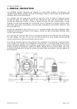
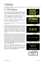
The ID5000A is a fully ATEX certified,

non-intrusive pig signaller which detects, 

signals and logs the passage of pigs at

critical points along the pipeline both on land

 and off shore

Summary of Contents for ID5000A

Page 1: ...ectronics com CHALLENGE ACCEPTED Non Intrusive Signaller Ultrasonic Active Topside Operating Manual The ID5000A is a fully ATEX certified non intrusive pig signaller which detects signals and logs the passage of pigs at critical points along the pipeline both on land and off shore ...

Page 2: ...of change A00 08 08 17 BG CR00485 Was ID5000A MANUAL RevB02 CR00380 Address change CR00499 Front cover update A01 12 10 17 BG CR00499 Cover page update A02 28 07 20 TL CR00800 Email address and Notified Body Number updated A03 15 10 20 TL CR00947 New Front Page Section 9 updated COMMENTS ...

Page 3: ... SET INDICATOR DELAY 9 3 3 13 SET MINIMUM DIAMETER 9 3 3 14 SET TIME 9 3 3 15 SET DATE 9 3 3 16 SET TRIG DELAY 10 3 3 17 SET FILTER 10 3 3 18 SET CONFIG 10 3 4 SETUP MODE 1 11 3 4 1 ZOOM AND RULER 12 3 4 2 THRESHOLD LEVELS 12 3 4 3 DETECTED DIAMETER 12 3 4 4 GAIN 12 3 4 5 PULSE WIDTH 12 3 4 6 SWITCH FUNCTION 13 3 4 7 DETECT VALUE 13 3 5 BATTERY INDICATOR 13 3 6 DETECTION ALGORITHM 14 4 INSTALLATIO...

Page 4: ...lection and the pig is detected Events are signalled as they occur via a 2 7 graphical display and high brightness LEDs positioned around the perimeter of the display Events can also be signalled remotely using several optional outputs The unit logs the time and date of up to 100 events which can be viewed at any point using the local display The user can turn the unit ON and OFF as well as modify...

Page 5: ...ays External Supply 24 0VDC Ambient Temperature Range See section 9 ATEX APPENDIX ATEX Code II 2 G Ex d mb IIC T5 T6 EC Type Examination Certificate Number TRL08ATEX21161X Housing Material SS Unit Only 316L Stainless Steel Housing Material Al Unit Only Copper Free Aluminium Alloy LM25 Al Transducer Material 316L Stainless Steel Weight in Stainless Steel 15kg Weight in Aluminium 11 5kg OUTPUTS SPDT...

Page 6: ... is calculating the diameter A switch press at this stage will have no effect After the unit is finished it will display the DETECTED DIAMETER screen The distance in the centre of this screen shows the average diameter which the unit detected The next line gives an idea of the quality of this signal path between 00 99 The measured diameter should be very close to the external diameter of the pipel...

Page 7: ...mined by the INDICATOR DELAY value See section 3 3 12 SET INDICATOR DELAY for a description of this parameter and how to alter its value SWITCH PRESS A single short press of the switch will enter the display menu interface described in section 3 3 SINGLE BUTTON MENU INTERFACE If the unit is not properly calibrated to a pipeline then it may repeatedly signal a PIG DETECTED message If this is the ca...

Page 8: ...y parameters simply follow the instructions provided on the screen All parameters are incremented by pressing the control button until they are at the desired value then allowing the timer to reach 0 If you do not wish to modify a parameter then simply allow the timer to reach 0 without operating the control button The menu system is designed so that the unit will always EXIT if the control button...

Page 9: ... are to be stored If this is not done then any changes to GAIN and PULSE WIDTH will be lost if SETUP MODE 1 is exited 3 3 7 MODE0 DETECT Accessed from SETUP MODE 1 Selecting this item leaves SETUP MODE 1 and enters DETECT MODE 0 If the SAVE GAIN AND PW item was not selected prior to this then any changes to their values will not be saved 3 3 8 ADJUST GAIN UP Accessed from SETUP MODE 1 This item ch...

Page 10: ...ed will be the time that the LEDs will flash every second for The seconds field will be the total number of seconds which the display shall show the pig detection time and date for E g if INDICATOR DELAY is set to 01 59 60 the unit will flash every second for 2 hours and for the first 60 seconds of this time it will show the pig passage time and date on the display 3 3 13 SET MINIMUM DIAMETER Acce...

Page 11: ...rmation 3 3 18 SET CONFIG Accessed from SETUP MODE 1 The SET CONFIG menu allows the user to enable special functions within the unit The number the CONFIG option is chosen by adding up the values for the desired options in the table below Option Number Effect when selected Invert Relay Operation 1 Relay will be normally closed and will open when signalling Debug display 2 Displays information usef...

Page 12: ...er side of the pipe Using the ruler along the bottom of the screen you can see that the first reflected signal in the above example occurs around 31cm from the injected pulse and this is confirmed by the value highlighted as the DETECTED DIAMETER This means that the unit is installed on a pipeline with a 31cm diameter As you can see from this example we are also seeing a secondary echo and if we z...

Page 13: ...WN and let the counter reach zero When the unit re enters the original screen the SWITCH FUNCTION field should contain G to tell the user that a short switch press will increment or decrement the GAIN When the user applies a short switch press the GAIN field will increment or decrement and the waveform should increase or decrease in amplitude In this way a weak reflection can be made to cross the ...

Page 14: ...y reaches a value greater than the user adjustable value DETECTION COUNT the unit will assume a pig passage Note that in SETUP MODE 1 the unit is only transmitting through the pipeline 10 times per second while in DETECTION MODE 0 it is transmitting 100 times per second See section 3 6 DETECTION ALGORITHM for more information 3 5 BATTERY INDICATOR The battery indicator is shown at the bottom right...

Page 15: ...ection is removed then DETECT will begin to rise if it reaches the same value as DETECT COUNT then a pig passage will be signalled 2 FILTER is a user adjustable value which can be set from 001 to 255 As can be seen this value is subtracted from DETECT every time the unit receives a good reflection from the far pipe wall If a reflection is seen then it is assumed that a pig passage cannot be taking...

Page 16: ...tact with the pipeline some precautions must be taken to avoid the cable becoming excessively twisted The figure below shows the preferred mounting positions for the system 4 1 MAIN HOUSING INSTALLATION 1 Referring to the figure above fit the main housing mounting plate onto the main housing mounting block with 4xM8x35 CAP screws and washers 2 Fit the main housing onto the mounting plate with 2xM8...

Page 17: ...uld take less than one turn to securely press the transducer face onto the pipeline surface 3 Apply couplant to the centre of the transducer face and to the area of pipeline surface where the transducer is to be installed 4 Securely strap the transducer assembly onto the pipeline surface so the transducer is transmitting horizontal If it is mounted vertically and there is a significant amount of g...

Page 18: ...is proportionally largest compared to the spurious signals before it However the overall signal strength has reduced to below the minimum signal level top horizontal line so we need to turn up gain again 4 After increasing the gain notice we now have a good strong signal well above the threshold level middle horizontal line the maximum signal level is above the minimum signal level and the spuriou...

Page 19: ...e in accordance with the manufacturers specifications Failure to use such components may invalidate the certification approval and may make the equipment dangerous 5 1 MAIN BATTERY REPLACEMENT 1 The Special Conditions for Safe Use detailed in section 9 ATEX APPENDIX of this manual must be observed and followed at all times 2 Referring to the figure below use a 3mm AF Hex key to loosen the locking ...

Page 20: ... the wires connected to the transducer cable are routed inside the housing before removing the 2x M4x25 cap screws holding the plastic battery compartment in place and carefully withdrawing the entire assembly out of the main housing While withdrawing the battery compartment be very careful not to damage any existing wiring 2 Observe how the transducer cable is connected to the assembly and then d...

Page 21: ...ct require repair due to a manufacturing deficiency during the guarantee period In the event of a manufacturing deficiency the inward transportation costs will be repaid to the client 8 DISPOSAL OF UNIT Online Electronics Ltd takes its responsibilities under the WEEE Regulations extremely seriously and has taken steps to be compliant in line with our corporate and social responsibilities In the UK...

Page 22: ...e using a suitable certified cable gland 6 For equipment with temperature class T5 cables must be suitable for use at temperatures of 100 C 7 Only ID5000A battery packs shall be used with the ID5000A 8 The battery pack must be removed if the external power supply is attached 9 Do not open enclosure nor replace battery packs when a potentially explosive atmosphere is present 10 The battery pack sha...

Reviews: