
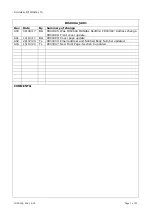


ONLINE ELECTRONICS LTD
ID5000A_5001_A03
Page 12 of 21
3.4.1.
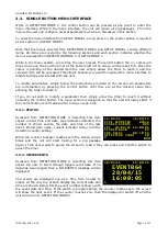
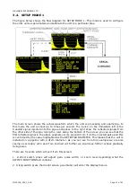
ZOOM AND RULER
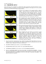
The ruler along the bottom of the screen allows the user to visually measure the diameter of a
pipeline by observing the position of any reflections along the ruler. The user can select one of
4 zoom levels which will show rulers of length 40cm, 80cm, 160cm or 320cm. The zoom level
is cycled by applying a short press on the switch while the SWITCH FUNCTION field is Z.
3.4.2.
THRESHOLD LEVELS
The horizontal lines are used to help calibrate the unit to a particular pipeline. The middle line
represents the THRESHOLD level of detection. To be detected a signal must cross this line. The
GAIN and PULSE WIDTH can be adjusted to make sure a signal crosses this threshold. The
position along the ruler where the first reflected signal crosses this line should match the value
shown in the DETECTED DIAMETER field. The upper and lower lines give a guide as to the best
minimum signal level and maximum noise level respectively.
3.4.3.
DETECTED DIAMETER
This field shows the pipe diameter which the unit is detecting. This should be checked by
looking at the waveform and noting the position of the first reflection along the RULER. GAIN
and PULSE WIDTH can be adjusted to make the waveform cross the THRESHOLD level.
3.4.4.
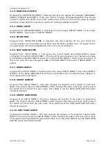
GAIN
The current GAIN is shown in this field and can have any value from 00-99.
An increase in gain will cause an increase in signal amplitude. To adjust the GAIN enter the
menus by pressing and holding the switch until the screen goes blank. Then cycle down to
ADJUST GAIN UP or ADJUST GAIN DOWN and let the counter reach zero. When the unit re-
enters the original screen the SWITCH FUNCTION field should contain G to tell the user that a
short switch press will increment or decrement the GAIN.
When the user applies a short switch press the GAIN field will increment or decrement and the
waveform should increase or decrease in amplitude. In this way a weak reflection can be made
to cross the THRESHOLD line and cause the correct DETECTED DIAMETER to be detected.
Once a suitable gain has been determined the value should be saved permanently by re-
entering the menus and selecting SAVE GAIN AND PW. If this step is not taken then when the
MODE is changed or the unit switched off the value will be lost.
3.4.5.
PULSE WIDTH
The current PULSE WIDTH is shown in this field and can have any value from 00-09.
The effect of changing pulse width is not always predictable but generally a wider pulse width
will cause more power to be injected into the pipe and result in stronger reflections. Normally
the PULSE WIDTH is left at the default value 01 and GAIN adjusted to increase signal strength.
To set the PULSE WIDTH enter the menus by pressing and holding the switch until the screen
goes blank. Then cycle down to AJST PULSE WIDTH on the second menu page and let the
counter reach zero. When the unit re-enters the original screen the SWITCH FUNCTION field
should contain W to tell the user that a short switch press will increment the PULSE WIDTH.
When the user applies a short switch press the PULSE WIDTH field will increment and the
effect should be seen on the waveform. Once a suitable PULSE WIDTH has been found SAVE
GAIN AND PW should be selected to save the value. If this step is not taken then when the
MODE is changed or the unit switched off the value will be lost.


