background image


- 1 -  

Revision 1.0 


  Operating Manual 


 OPP Series On-Line UPS 


Summary of Contents for OPP Series

Page 1: ... 1 Revision 1 0 Operating Manual OPP Series On Line UPS ...

Page 2: ...onfiguration and troubleshooting It also includes a section on software installation and general connectivity The specification section outlines all of the detailed parameters of operation of the OPP UPS and provides general information on approvals and certification The UPS should be installed according to the instructions in this manual Failure to do so could result in safety issues It could als...

Page 3: ... and must not be dropped Installation Do not operate the equipment in the presence of flammable gases or fumes Operation of any electrical equipment in such an environment constitutes a safety hazard Do not place the UPS in an unventilated room or enclosure The UPS must be installed in accordance to the instructions within this manual Failure to recognise the electrical hazards could prove fatal D...

Page 4: ...e they are disposed of properly Refer to your local codes for disposal requirements Never dispose of batteries in a fire Batteries may explode when exposed to flame Replace batteries with the same number and type of batteries or battery packs as originally installed in the equipment ...

Page 5: ... 2 Free standing configuration 14 3 3 Rack mount configuration 16 3 4 Rear panel features 17 3 5 Power connection OPP1000 OPP1500 18 3 6 Power connection OPP2500 OPP3000 19 3 7 Power connection OPP4000 OPP6000 21 3 8 Communication connectivity 23 3 9 RS232 24 3 10 REPO 26 4 Operation 28 4 1 Description of front panel features 28 4 2 Starting shutting down the UPS Bypass 29 4 3 Using the front pane...

Page 6: ...rouble shooting guide 38 5 2 LCD trouble shooting guide 40 5 3 Replacing batteries 42 6 Software set up 44 6 1 General windows software installation 44 7 Specification 48 7 1 General specification 48 7 2 Run time chart 50 7 3 Fixing centres dimension tables 52 ...

Page 7: ...erview Under normal conditions mains is fed into the rectifier which provides DC power to the Inverter and DC via the charger to charge the batteries The inverter then feeds the load continuously If the primary mains supply fails the UPS simply uses the secondary supply if connected thus maintaining power to the load without using it s batteries If the auxiliary and primary supply fail then the UP...

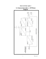
Page 8: ... 8 Revision 1 0 General Description 1 2 General description OPP Block Diagram ...

Page 9: ...ugh that they are considered a one man lift so shipping installation is much easier Dual mains input Most UPS have one mains input however the OPP has 2 It is common for comms rooms to be fed from 2 supplies possibly 2 phases of the same supply so that if there is a problem on one supply the other can take over and prevent the UPS from needing to discharge its batteries until there is no other opt...

Page 10: ... space becomes limited and give the option of free standing it without the need to purchase a different model Rotating Back lit LCD for monitoring and control OPP has a fully rotating back lit LCD which shows load voltage temperature etc which is simply twisted to be the right way up This makes the UPS much more user friendly especially if it s in a poorly lit room i e during power failure conditi...

Page 11: ...equired OPP3000 1 battery module 2 boxes required OPP4000 2 battery modules 3 boxes required OPP5000 2 battery modules 3 boxes required OPP6000 2 battery modules 3 boxes requried If there are not enough boxes to make up the UPS please contact order point immediately This is clarified in the drawings below OPP1000 OPP1500 UPS uses one standard battery pack behind the panel on the left hand side of ...

Page 12: ...is also shipped with software and racking ears for 19 shelf mounting A full list of the box contents is provided below OPP1000 OPP1500 OPP2500 OPP3000 1 box contains 2 boxes contain Box 1 UPS module with fitted batt UPS electronics module Input cables x 1 Input cable x 1 4 way distribution block output cable x 2 REPO connector REPO connector RS232 cable RS232 Cable Software CD Software CD Manual 1...

Page 13: ... 3 boxes contain Box 1 Box 2 UPS Electronics module Battery module REPO connector Battery connection cable RS232 Cable 19 rack ears screws Software CD 1 set key lock bolts Manual 19 rack ears screws Box 3 Battery module Battery connection cable 19 rack ears screws 1 set key lock bolts ...

Page 14: ...o C to 25o C is recommended Provide shelter from moisture Make sure that ventilation and space requirements are met Maintain clearance at front of UPS for user operations Ensure that the air vents at the front and rear are not blocked 3 2 Free standing configuration When using the UPS free standing the unit should be mechanical stood vertically As shown below OPP1000 OPP1500 Free standing OPP2500 ...

Page 15: ...to lock units together when located beside each other in free standing mode This key lock function is also available as standard if additional battery packs are added to either OPP1000 OPP1500 or OPP2500 OPP3000 The OPP4000 OPP5000 OPP6000 key lock together in the same way as the OPP2500 OPP3000 The drawing above shows how to use the feet supplied as standard with the OPP1000 OPP1500 if used in fr...

Page 16: ...000 Rack mount The ears supplied are not designed to support the weight of the UPS The UPS must either be support on guides or on a shelf within the 19 cabinet Telescopic rack guides can be supplied as an optional part code OPP R Each module needs to be fitted with Telescopic guides Therefore when ordering an OPP6000 with the R option The constructed part number should be OPP6000R This will provid...

Page 17: ... 17 Revision 1 0 Installation and Set up 3 4 Rear Panel Features ...

Page 18: ...pply Two IEC input sockets are available Main IEC input and Auxiliary IEC input If a single mains supply is available only then the input power cord should be connected to the Main input socket If two supplies are available then both IEC inlets can be used Distribution outlets are available via the 4 way IEC distribution block provided ...

Page 19: ...ttery connector covers must first be removed See diagram below Once this has been done the battery cable supplied can be connected between battery connector on UPS and battery connector on Battery module The cable supplied has a simple push fit Anderson connector at each end When the cable has been connected the battery breaker must be switched to the ON position ...

Page 20: ...available only then the input power cord should be connected to the Main input socket If two supplies are available then both IEC inlets can be used Two output sockets are available from the unit Main and load segment controlled output two These are both 16A IEC outlets If load segment control is not required then both receptacles can be used If it is required to shutdown one output independently ...

Page 21: ...le to the UPS on the OPP4000 OPP6000 the battery connector cover must first be removed See diagram below Once this has been done the battery cables supplied can be connected between battery connector on UPS and battery connector on each battery module The cable supplied has a simple push fit Anderson connector at each end ...

Page 22: ...P4000 OPP6000 cont The Hardwire termination for the OPP4000 OPP6000 provides input connection for the main supply auxiliary supply as well as output connection Connector Ratings and cable sizing Hardwire terminations will accept 10AWG 6mm2 cable for input and output wiring ...

Page 23: ...ith the following communication ports Main RS232 port fixed Auxiliary RS232 port fitted into option slot REPO remote emergency power off port The unit is supplied with one RS232 cable and one mating half REPO connector The RS232 cable will provide communications to a local computer using the supplied Cruiser software package ...

Page 24: ...dapter SNMP fits in place of the option slot RS232 Order code OPP S AS400 Volt free contact board fits in place of the option slot RS232 order code OPP V USB card fits in place of the option slot RS232 Order code OPP USB 3 9 RS232 detail Main RS232 pin details DB 9 Pins of the connector are as following figure PIN PIN Definition UPS PIN Definition PC 2 Transmitted data Received data 3 Received dat...

Page 25: ...ls Pin out for the second RS232 port is as standard the same as the first However this can be changed to the format as shown below by removing the card and setting the 4 jumpers on the card to Megatec positon from the PC position This should only be done when UPS is off ...

Page 26: ...ns where REPO is required use the following procedure Operating the REPO The REPO feature shuts down the protected equipment immediately and does not follow the orderly shutdown procedure initiated by any power management software Any devices which are operating on battery are also shut down immediately When the REPO switch is closed the equipment will not return to battery power until the UPS inp...

Page 27: ...m 30Vac RMS maximum and 20mA maximum between pins 1 and 2 as shown below Use stranded non shielded wiring size 18 22 AWG Replace the REPO connector into rear of UPS Verify that the externally connected REPO switch is off to enable power to the UPS output receptacles Plug in the UPS and start the UPS by pressing the input breaker to ON Turn on the external REPO switch to test REPO function Turn off...

Page 28: ...hown above A retaining screw is then used to fix the panel in place Never rotate panel whilst UPS is on Front Panel Buttons Turn on off the inverter or force unit to bypass Start UPS from battery when mains is not available Select the status shown in the first row or move forward to next function or parameter Select the status shown on the second row or setting the function or parameter Enter the ...

Page 29: ...ch the input breaker on the front panel rear panel for OPP4000 OPP5000 OPP60000 to ON position The LCD should show the model number The UPS should then beep and cycle through its start up procedure Once the UPS powers up and self check is successful then power will be supplied to the output receptacles The default indication at this stage on the UPS display should be ...

Page 30: ... UPS has been shutdown such that no data is lost when unit is switched off Push and hold the until the UPS beeps The UPS is now in bypass mode and running from mains input Now turn the input breaker to the OFF position this will cut the power to the UPS thus shutting the UPS down If this shutdown is over an extended period of time weeks then the battery breaker should also be switched to the OFF p...

Page 31: ...r This condition cannot be reset please contact your UPS supplier If the UPS is forced to bypass as described in 4 2 In any case the user can identify if the UPS goes into bypass by the beep that is made and when in bypass the UPS displays Bypass Mode on the top line of the LCD display 4 3 Using the front panel Accessing the menu functions from the front panel allows the user to confirm a number o...

Page 32: ... are nine display parameters available using the above method as defined below OP A Output current IP V Input Voltage OP V Output Voltage OP F Output Frequency BT V Battery Voltage Load percent of Load T EN temperature of environment T HS temperature of the internal heat sink The button used to edit the parameters within the UPS is Use the key to enter edit mode of the UPS Functions and parameters...

Page 33: ...ow disabled Using the button 1st press Green Mode EN Enable Green Mode DIS Disable Green Mode Green mode allows the user to set the unit to run directly from the mains when the load is less than 5 If the load increases then the unit will switch back to On line mode This improves efficiency under low load running conditions 2nd press Buzzer Silent see example page 30 EN Enable the Buzzer Silent fun...

Page 34: ...n 4th press Test Mode Press the key for testing the UPS battery The display will show test fail if the UPS Battery is found to be faulty The battery will need replacing urgently the UPS may not be able to support the load under mains fail conditions 5th press Load Segment Control LB Load Control active when Low Battery LF Load Control active when Line Voltage Fail DIS Disable the Load Control func...

Page 35: ...lso form part of the trouble shooting guide Audible Alarms Battery Mode DC Mode ___ ____ Battery Low ___ ___ ____ ____ ____ Line Voltage fault ____ ____ ____ Line Frequency fault __ __ __ __ Over Temperature __ __ __ __ __ Input Over Current __ __ __ __ __ __ Overload or UPS Fault ________ Charger Fault ___ ____ ____ Key ____ Buzzer On Buzzer Off ...

Page 36: ...n the bottom line unless changed by the user Input and Output voltages will change dependant on the UPS location a settings The UPS should make no audible alarm noise This then indicates that power is being supplied to the load and the system is functioning normally If a further test is required then use the self test function to check the UPS operation See using the front panel on page 21 ...

Page 37: ...input parameters i e Exceeds or is lower than specified input voltage range Exceeds or is lower than specified input frequency range The default display will be DC Mode on the top line and output voltage on the bottom line if mains has failed OPV may vary dependant on settings The unit will emit the following Audible alarms Utility out of specification two short beeps repeating Battery low at end ...

Page 38: ...hooting guide UPS will not provide power to the load Power only present on one output If 2 5kVA or 3kVA unit check load receptacle segment control setting See page 34 No output from output cable Check cable is correctly installed into rear of UPS Output fails as soon as load connected make sure that load does not exceed maximum rating of UPS UPS operates from battery despite mains being available ...

Page 39: ...function as described on page 34 If Expected battery reported faulty see changing the battery in maintenance section 5 2 Check to see load has not increased this will reduce run time available from battery Shed non critical load when mains fails Use load segment function which allows the user to switch off non critical items of load on mains failure or battery low UPS Beeping The UPS is beeping an...

Page 40: ...s displayed on the panel can be read as follows The DC bus voltage exceeds high set point contact Point of sale The DC bus is out of specified limits contact point of sale Inverter voltage over high set point contact point of sale Inverter voltage under low set point contact point of sale ...

Page 41: ... Trouble shooting cont Output current over high set point Check UPS for overload Battery Voltage under low set point UPS battery low faulty DC Bus voltage under low set point contact point of sale Inverter frequency error contact point of sale ...

Page 42: ... indicated below Fixing Screws Battery panel This can be done by removing two fixing screws as indicated Once this panel has been removed the retaining plate needs to be unscrewed and removed before access is available to the battery pack The battery pack can then be simply withdrawn as shown below Warning Removing the battery whilst the unit is supporting load could result in loss of power to loa...

Page 43: ... the handles provided and replacement packs can be fitted Battery modules can be isolated from UPS if required by switching off the battery breaker on the rear of the battery module Warning Removing the battery whilst the unit is supporting load could result in loss of power to load if mains fails during battery replacement Number of battery packs required OPP1000 OPP1500 will need 1 pack unless s...

Page 44: ...tep guide is for Windows based operating systems For installation instructions for other operating systems please consult software manual as supplied on CD Place Cruiser CD in drive and it will auto run install program as follows if not select set up from file menu on CD Step 1 Click Next to continue ...

Page 45: ... 45 Revision 1 0 Software Set up 6 1 General windows software installation cont Step 2 Type in User Name and Company Name Step 3 Type in the Serial Number ...

Page 46: ... 46 Revision 1 0 Software Set up 6 1 General windows software installation cont Step 4 Choice the Destination Folder Step 5 Restart the computer ...

Page 47: ... 47 Revision 1 0 Software Set up 6 1 General windows software installation cont Step 6 The setup process will create the Cruiser program group in Programs Files and add its icon ...

Page 48: ... 48 Revision 1 0 7 Specification 7 1 General specification ...

Page 49: ... 49 Revision 1 0 Specification 7 1 General specification cont ...

Page 50: ... 50 Revision 1 0 Specification 7 2 Run time chart OPP1000 OPP3000 For extended run times above and beyond those shown here please contact point of sale ...

Page 51: ... 51 Revision 1 0 Specification 7 2 Run time chart OPP4000 OPP6000 ...

Page 52: ... 52 Revision 1 0 Specification 7 3 Fixing centres and Dimension tables Rack mount Fixing centres for Guides OPP R OPP Dimensions OPP Weights ...

Reviews: