background image

M A I N T E N A N C E  

124 / 222 


XS700-XS3000_manual_ger_eng_it_V1.1.2.doc

 ........................................................... 

R. Kistler 


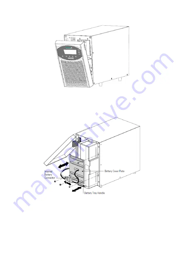
Figure 14: Removing the front cover from the UPS system 

2.  Unscrew  the  two  screws  that  secure  the  plug  connection  in 

place these to the side. Disconnect the  internal battery plug 
connection (see Figure 15). 


Figure 15: Replacing the internal batteries of the UPS system 

3.  Unscrew  the  two  screws  that  secure  the  battery  cover  and 

place  these  to  the  side.  Grab  the  battery  cover  at  a  corner 
and pull  it  carefully  forwards.  The  battery  cover  can  now  
be removed and placed to the side (see Figure 15). 

Summary of Contents for ONLINE XANTO S 1000

Page 1: ... Deutschland Italien Schweiz ONLINE USV Systeme AG Dreimühlenstraße 4 D 80469 München Phone 49 89 2423990 10 Fax 49 89 2423990 20 www online usv de ONLINE UPS Systems S r l Via Gilera Ferruccio 110 I 20862 Arcore MB Phone 39 039 2051444 Fax 39 039 2051435 www online ups it ONLINE USV Systeme AG Eigenheimstraße 11 CH 8304 Wallisellen Zürich Phone 41 44 9452829 Fax 41 44 9453288 www online usv ch ...

Page 2: ...2 222 XS700 XS3000_manual_ger_eng_it_V1 1 2 doc R Kistler ...

Page 3: ...er Sprache 23 4 1 2 Anzeigefunktionen 23 4 1 3 Anwenderprogrammierung 24 4 2 Betriebsarten 28 4 2 1 Normalbetrieb 28 4 2 2 Batteriebetrieb 28 4 2 3 Bypassbetrieb 29 4 2 4 Standbybetrieb 30 4 3 Starten und Abschalten der USV Anlage 30 4 3 1 Starten der USV Anlage 30 4 3 2 Starten der USV Anlage im Batteriebetrieb 31 4 3 3 Abschalten der USV Anlage 32 4 4 Betriebsartwechsel der USV Anlage 32 4 5 Ein...

Page 4: ... 1 Austausch der internen Batterien des Tower Modells 49 7 4 2 Austausch des Batteriepaketes des Tower Modells 52 7 4 3 Austausch der internen Batterien des Rack Modells 53 7 4 4 Austausch des Batteriepaketes vom Rack Modell 55 7 5 Testen der neuen Batterien 57 7 6 Entsorgen der Altbatterien oder der USV Anlage 58 8 Fehlerbehebung 59 8 1 Typische Warn und Statusmeldungen 59 8 2 Stummschalten des W...

Page 5: ...nikationsoptionen Modell XANTO S 3000R 39 Abbildung 11 RS 232 Kommunikationsschnittstelle DB 9 Stecker 40 Abbildung 12 Notaus Anschluss 43 Abbildung 13 Anschlüsse der Standard Relais Schnittstelle 44 Abbildung 14 Entfernen der Frontblende von der USV Anlage 50 Abbildung 15 Austauschen der internen Batterien der USV Anlage 50 Abbildung 16 Entfernen der Frontblende von der USV Anlage 53 Abbildung 17...

Page 6: ... Versorgungsnetz fällt häufig dann aus wenn man es am we nigsten erwartet und die Qualität der Stromversorgung kann oft er heblichen Schwankungen unterliegen Netzprobleme können dazu führen dass kritische Daten zerstört werden ungesicherte Daten verloren gehen und Hardware beschädigt wird was zu teuren Repa raturen und Ausfallstunden führt Mit der XANTO S werden Ihre Anlagen vor Stromversorgungspr...

Page 7: ...atz sparender 2U Größe die in jedes 48cm 19 Standardrack passen RS 232 und USB Schnittstelle Relais Ausgangskontakte Slot für optionale SNMP Adapter AS400 oder Relais Karte Notaus Funktion Remote Emergency Power Off Abbildung 1 XANTO S Tower und das optionale Batteriepaket Abbildung 2 XANTO S Rack und das optionale Batteriepaket ...

Page 8: ... Wechselstromquel le angeschlossen ist Um Brandgefahr oder das Risiko eines elektrischen Schla ges zu verringern darf die USV Anlage nur in Gebäuden mit kontrollierter Temperatur und Luftfeuchtigkeit installiert wer den in denen keine leitenden Schmutzstoffe vorhanden sind Die Umgebungstemperatur darf 40 C nicht übersteigen Die USV Anlage darf nicht in der Nähe von Wasser oder in ex trem hoher Luf...

Page 9: ...aßnahmen Die Wartung muss von qualifiziertem Personal durchgeführt wer den das im Umgang mit Batterien geübt ist und über gute Kenntnisse der erforderlichen Vorsichtsmaßnahmen verfügt siehe Wartung Halten Sie nicht autorisiertes Personal von Batterien fern Die Batterien müssen ordnungsgemäß entsorgt werden Hierbei sind die örtlichen Bestimmungen zu beachten Batterien dürfen nicht verbrannt werden ...

Page 10: ... wird kann es zu Kondensatbildung innerhalb und außerhalb des Gehäuses kommen Installieren Sie die USV Anlage nur wenn Innen und Außenseite vollständig trocken sind Gefahr eines elektrischen Schlages Die USV Anlage hat ein hohes Gewicht siehe Technische Daten Vorsicht beim Auspacken und Transportieren der USV HINWEIS Bewegen und öffnen Sie die verpackte USV Anlage vorsich tig Lassen Sie die Kompon...

Page 11: ...O S 1500R Batteriepaket XANTO S 2000R 3000R 19 Montagewinkel links und rechts 2 2 2 2 2 2 2 2 RS 232 Schnittstellen kabel 1 1 1 1 1 1 1 1 1 1 10A Kaltgeräteverlänge rung 2 3 3 4 4 2 3 3 4 4 16A Netzanschlusskabel 1 1 Batteriekabel 1 1 1 Software DataWatch 1 1 1 1 1 1 1 1 1 1 Bedienungsanleitung 1 1 1 1 1 1 1 1 1 1 Tabelle 1 Lieferumfang 3 4 Installation des Tower Modells 3 4 1 Mechanischer Aufbau ...

Page 12: ... der Garantieanspruch verloren geht Verbinden Sie das Anschlusskabel der USV Anlage nicht mit dem Versorgungsnetz bevor die Installation vollständig ab geschlossen ist 1 Wenn Sie die DataWatch Software installieren verbinden Sie Ihren Computer mit einer der Schnittstellen Verwenden Sie für die Schnittstellen ein geeignetes Kabel RS 232 Kabel ist im Lieferumfang enthalten 2 Falls ein Not Aus Schalt...

Page 13: ...der zweite Batterieanschluss ab gedeckt siehe Abbildung 3 Bewahren Sie alle Klemmen und Schrauben auf ACHTUNG Ein kleiner Lichtbogen kann auftreten wenn das Batteriepa ket an die USV Anlage angeschlossen wird Das ist normal und kann nicht zur Gefährdung von Personen führen Führen Sie das Kabel des Batteriepaketes schnell und kräftig in die Batterie Steckverbindung der USV Anlage ein 4 Verbinden Si...

Page 14: ...das Batteriepaket wird vollständig zusammenge baut und anschlussfertig geliefert Für das Rack Modell werden optionale Gleitschienen Art Nr Rack Kit angeboten Die Gleitschienen sind passend für 48 cm 19 Zoll Racks mit einer Bautiefe von 61 bis 76 cm 24 bis 30 Zoll HINWEIS Pro USV Anlage und pro Batteriepaket ist ein Rack Kit not wendig 1 Montage des Rack Kits siehe separate Montageanleitung ...

Page 15: ...ner für die mittlere Position vorgesehen Wählen Sie die Position nach Ihrem Konfigura tionsbedarf 4 Wenn Sie zusätzliche USV Anlagen oder Batteriepakete in stallieren wiederholen Sie die Schritte 2 und 3 5 Schieben Sie die USV Anlagen und die Batteriepakete in das Rack 6 Befestigen Sie die Front der USV Anlage bzw des Batteriepa ketes am Rack Verwenden Sie hierfür auf beiden Seiten zwei M6 x 16 Fl...

Page 16: ... Rack über Erdungsleiter oder Leiter für den Potenzi alausgleich zwischen Metallteilen verfügt verbinden Sie das Erdungskabel nicht mitgeliefert mit der für den Erdungsan schluss vorgesehenen Schraube Im Abschnitt Technische Daten finden Sie Hinweise für die jeweilige Lage der Erdungs schraube für jedes Modell 3 Falls ein Not Aus Schalter vorgeschrieben ist finden Sie Hin weise zur Installation im...

Page 17: ...e der Front blende der USV Anlage siehe Abbildung 6 HINWEIS Gehen Sie vorsichtig vor um das LCD Anzeige und Bedien feld und das angeschlossene Flachbandkabel nicht zu be schädigen Abbildung 6 Entfernen des Kabelauswurfs vom Batteriepaket 3 Entfernen Sie die Frontblende von jedem einzelnen Batte riepaket siehe Abbildung 7 Um die Blende zu entfernen lösen und entfernen Sie die bei den Schrauben an d...

Page 18: ...ACHTUTNG Ein kleiner Lichtbogen kann auftreten wenn das Batteriepa ket an die USV Anlage angeschlossen wird Das ist normal und kann nicht zur Gefährdung von Personen führen Führen Sie das Kabel des Batteriepaketes schnell und kräftig in die Batterie Steckverbindung der USV Anlage ein 6 Stecken Sie das Kabel des Batteriepaketes in den Batteriean schluss der USV Anlage wie in Abbildung 8 dargestellt...

Page 19: ...cht lösen Angemessene Biegeradien und Zugentlas tungen für alle Kabel müssen vorhanden sein Abbildung 8 Typische Installation meherer Batteriepakete 8 Einsetzen der Frontblende des Batteriepaketes Um die Blende wieder einzusetzen stellen Sie sicher dass die Kabel des Batteriepaketes durch die Kabelauswürfe ge führt sind Schieben Sie anschließend die Blende nach rechts bis sie in die Halterung an d...

Page 20: ...e bei 3000VA Modell im Lieferumfang Das LCD Display an der Frontblende der USV Anlage leuchtet auf und zeigt das ONLINE Logo an 5 Drücken Sie die Taste an der Frontblende der USV Anlage mindestens eine Sekunde lang Das Display zeigt den Status UPS starting an 6 Falls das Display der USV Anlage aktive Warnmeldungen an zeigt beheben Sie die Probleme bevor Sie mit der Inbetrieb nahme fortfahren siehe...

Page 21: ... den Wert der Eingangsfrequenz gesetzt die automatische Er kennung ist standardmäßig aktiviert Beim ersten Starten wird die Ausgangsspannung auf 230V gesetzt die automatische Erkennung ist standardmäßig de aktiviert 11 Falls ein zusätzlicher Notaus Schalter installiert wurde muss die Notaus Funktion geprüft werden Betätigen Sie hierzu den Notaus Schalter und überprüfen Sie den Statuswechsel auf de...

Page 22: ...atterieeinstellungen und Kommunikation 4 1 Funktionen auf dem Bedienfeld Abbildung 9 XANTO S Bedienfeld Modell XANTO S 3000R Anzeige Status Beschreibung Grün EIN Die USV Anlage läuft im Normalbetrieb Blinkt Eine neue Informationsmeldung ist aktiv Gelb EIN Die USV Anlage befindet sich im Batteriebetrieb Blinkt Die Batteriespannung liegt unterhalb der Warnmeldungs schwelle Gelb EIN Die USV Anlage be...

Page 23: ...gen Menü zurückkehren Hauptmenu Untermenü Anzeigeinformation der Menüfunktion USV Status Hauptstatus Betriebsart und Last Hinweis oder Warnstatus sofern vorhanden Batte riestatus Status und Ladestand Ereignis aufzeichnung Zeigt bis zu 127 Ereignisse und Warnmeldun gen an Messwerte Last W VA Last A pf Ausgang V Hz Eingang V Hz Bypass V Hz Ereignisse des Eingangsstroms Batterie V min Kontrolle Auf B...

Page 24: ...rden in englischer Sprache angezeigt Empfehlung auf Deutsch ändern Englisch User Passwort Aktiviert Deaktiviert Im Modus Aktiviert lautet das Kennwort USER Empfehlung nicht ändern Deaktiviert Akustische Warn signale Aktiviert Deaktiviert Empfehlung nicht ändern Aktiviert Datum und Zeit einstellung Datum yyyy mm dd Zeit hh mm Empfehlung Datum einstellen 2008 01 01 12 00 Signaleingänge Siehe Program...

Page 25: ...ffizient Siehe Einstellen der Energiestrategie Empfehlung nicht ändern Normal Verzögerung Auto Start Deaktiviert Keine Verzögerung 1s 2s 32767s Im Modus Deaktiviert ist der automatische Neustart nicht erlaubt siehe Konfigurieren von Lastsegmenten Empfehlung an Erfordernisse anpassen Segment 1 Keine Verzögerung Segment 2 Keine Verzögerung Autom Shutdown im Batteriebetrieb Deaktiviert Keine Verzöger...

Page 26: ... die USV Anlage in Betrieb ist Der Bypassbe trieb wird deaktiviert Sonderfall IT System frz Isolé Terre Z B in Krankenhäusern Schiffen und Bahn auf De aktiviert ändern Sonst startet USV Anlage nicht Empfehlung nur bei Sonderfall ändern Aktiviert Unterer Schwellenwert Bypass Spannung 4 5 20 der Nennspannung Siehe Konfigurieren der Bypass Einstellungen Empfehlung nicht ändern 15 der Nennspan nung Ob...

Page 27: ... Wenn ein Prozentsatz gewählt ist erfolgt der automatische Neustart sofern aktiviert wenn die Batterieladung den gewählten Wert er reicht Empfehlung an Erfordernisse anpassen Ungeprüft Batterieladung niedrig Alarm Sofort 2Min 3min 5Min Empfehlung an Erfordernisse anpassen 3min Automatische Bat terietests Aktiviert Deaktiviert Siehe Ausführen der automatischen Batterie tests Empfehlung nicht ändern...

Page 28: ...t 24 Stunden lang im Hochalarm Betrieb oder bis dieser Betrieb durch einen Befehl der Energiestrategie geändert wird bevor sie in die vorherige Betriebsart zurückschaltet Die optionalen Einstellungen für High Efficiency Hocheffizienz und Energiestrategie minimieren die Wärmeabgabe an die Rack Umgebung siehe Anwenderprogrammierung 4 2 2 Batteriebetrieb Wenn die USV Anlage während eines Netzausfalls...

Page 29: ...eiterhin passiv von der USV Anlage gefiltert Die Anzeige leuchtet auf Die USV Anlage verbleibt mindestens 5 Sekunden lang im By passbetrieb sofern die Qualität der Bypass Quelle akzeptabel bleibt Wenn drei Wechsel in den Bypassbetrieb innerhalb von 10 Minuten erfolgen ohne dass diese durch einen manuellen Befehl vom Benutzer eingegeben wurden wird die USV Anlage 1 Stunde lang oder bis zum Betätige...

Page 30: ...lle sinkt Es gilt die jeweils zuerst auftretende Bedingung Falls das Netz ausfällt während sich die USV Anlage im Standby Betrieb befindet schaltet sich die Stromversorgung der Steuerung nach etwa 10 Sekunden aus Falls die USV Anlage auf Befehle wartet und der Strom ausfällt schalten sich das Gerät und die Stromversorgung der Steuerung nach etwa 30 Sekunden aus 4 3 Starten und Abschalten der USV A...

Page 31: ...Normalbetrieb befinden 7 Drücken Sie die esc Taste bis der Startbildschirm angezeigt wird 4 3 2 Starten der USV Anlage im Batteriebetrieb HINWEIS Vor der Verwendung dieser Funktion muss die USV Anlage mindestens einmal vom Netz versorgt und aktiviert worden sein Das Starten im Batteriebetrieb kann deaktiviert werden sie he Starten im Batteriebetrieb unter Anwenderprogrammie rung 1 Drücken Sie die ...

Page 32: ...tatus USV vor Abschaltung an Die USV Anlage wechselt dann in den Standby Betrieb und das Display schaltet sich aus HINWEIS Wird die Taste nach weniger als drei Sekunden losgelas sen so kehrt die USV Anlage wieder zu ihrer vorherigen Be triebsart zurück 2 Schalten Sie das Versorgungsnetz für den Stromkreis aus an den die USV Anlage angeschlossen ist 4 4 Betriebsartwechsel der USV Anlage Vom Normal ...

Page 33: ...berlast Standardmäßig wird ein Wechsel in den Bypassbetrieb erzwungen wenn eine Überlastung auftritt Sie können die Einstellung für einen verzögerten Wechsel konfigurieren Die Wartezeit richtet sich dabei nach dem Grad der Überlastung siehe Tabelle 15 Elektrische Ein und Ausgangsleis tung unter Technische Daten Unterer Schwellenwert Bypass Spannung Standardmäßig ist ein Wechsel in den Bypassbetrie...

Page 34: ...dem Bypass zu synchronisieren wenn die Bypass Frequenz unterhalb des für die Einstellung Synchronisierungsfenster festgelegten Wer tes liegt Liegt die Bypass Frequenz oberhalb des eingestellten Wer tes wechselt die USV Anlage zur Normalfrequenz Im Bypassbe trieb beträgt das Synchronisierungsfenster 5Hz Ist die Synchroni sierung deaktiviert Synchronisation deakt so synchronisiert sich die USV Anlag...

Page 35: ...ste um die Auswahl zu bestätigen 3 Stellen Sie das andere Lastsegment ein sofern benötigt So stellen Sie die Wartezeiten für Neustart und Abschaltung der ein zelnen Lastsegmente ein 1 Drücken Sie auf eine beliebige Taste um die Menüoptionen zu aktivieren Wählen Sie EINSTELLUNGEN ANWENDER PROGRAMMIERUNG und anschließend VERZÖGERUNG AUTO START aus 2 Stellen Sie die Wartezeit für den Neustart eines L...

Page 36: ...iguration mithilfe der oder Taste aus Anzahl der Batterie Strings Alle USV Anlagen und Batteriepakte 0 Nur USV Anlage keine internen Batterien 1 Standard Nur USV Anlage interne Batterien 3 USV Anlage 1 Batteriepaket 5 USV Anlage 2 Batteriepakete 7 USV Anlage 3 Batteriepakete 9 USV Anlage 4 Batteriepakete Tabelle 5 Anzahl der Batteriereihen HINWEIS Falls 0 gewählt wurde sind keine internen Batterie...

Page 37: ...terien müssen vollständig aufgeladen sein Die Bypass Spannung muss akzeptabel sein Kein manueller Batterietest wurde vorher in demselben Auf ladezyklus initiiert Damit der Batterietest bestanden wird muss die Batteriespannung während des Entladens oberhalb des Schwellenwertes bleiben 4 8 3 Konfigurieren des automatischen Neustarts Nach Abschaltung der USV Anlage z B durch leere Batterien bei Strom...

Page 38: ...frequenz ist z B für empfindliche Verbraucher erforderlich 1 Drücken Sie eine beliebige Taste um die Menüoptionen zu aktivieren Wählen Sie EINSTELLUNGEN ANWENDER PROGRAMMIERUNG und anschließend FREQUENZUM RICHTER aus 2 Wählen Sie AKTIVIERT und bestätigen Sie mit der Taste 3 Wechseln Sie anschließend zu AUSGANGSFREQUENZ 4 Wählen Sie 50Hz oder 60Hz und bestätigen Sie mit der Taste Ist das Versorgung...

Page 39: ...NTO S hat serielle RS 232 und eine USB Kommunikati onsschnittstelle sowie einen Slot für optionale Schnittstellenkarten HINWEIS Sie können Ausgangskontakte Signaleingänge und Baudra te der seriellen Schnittstelle mithilfe der Menüs auf dem Be dienfeld konfigurieren siehe Tabelle Anwenderprogrammie rung Die Datenübertragungsgeschwindigkeit der USB Schnitt stelle ist auf 2400 Baud festgelegt ...

Page 40: ...SV Anlage Daten austauschen siehe DataWatch Software Die Software ruft bei der USV Anlage detaillierte Anga ben zum Status der Stromversorgungsumgebung ab Falls eine Not stromversorgung erforderlich wird löst die Software das Speichern sämtlicher Daten und ein ordnungsgemäßes Abschalten der Anlage aus Die Belegung der Kabelanschlussstifte für die RS 232 Kommuni kationsschnittstelle ist in Abbildun...

Page 41: ...inem Slot siehe Abbildung 10 für die folgen den Schnittstellenkarten ausgestattet Art Nr Beschreibung DW7SNMP30 SNMP Adapter Basic Der SNMP Adapter kommuniziert via TCP IP mit den ange schlossenen Verbrauchern im Netzwerk DW5SNMP30 SNMP Adapter Professional Funktion wie Basic jedoch mit zusätzlicher Schnittstelle für Tem peraturfühler und Gebäudemanagement PHXNOV I Relais Einschubkarte Meldung von...

Page 42: ... darf nicht an Schaltkreise angeschlos sen werden die mit dem Versorgungsnetz verbunden sind Eine verstärkte Isolierung zum Netz ist erforderlich Der Notaus Schalter muss mindestens für 24V und 20mA ausge legt sein Es muss ein Öffner verwendet werden Für den ordnungsgemäßen Betrieb muss die Notaus Funktion min destens 250ms lang aktiv bleiben Wenn die die Notaus Funktion aktiviert wird muss zusätz...

Page 43: ...instellen Siehe die Einstellung Po larität des REPO Eingangs unter Anwenderprogrammierung HINWEIS Je nach Benutzerkonfiguration müssen die Kontakte geöffnet Empfehlung oder geschlossen werden um den Betrieb der USV Anlage aufrechtzuerhalten Schließen Sie zum Neustar ten der USV Anlage die REPO Anschlusskontakte bzw öff nen Sie diese erneut und schalten Sie die USV Anlage von Hand ein Der maximale ...

Page 44: ...stellen siehe Abbildung 10 ACHTUNG Der Relais Ausgangskontakt darf nicht an Schaltkreise an geschlossen werden die mit dem Netz verbunden sind Eine verstärkte Isolierung zum Netz ist erforderlich Der Relais Ausgangskontakt hat maximale Nennwerte von 30VAC 1A und 60VDC 2A Signal Beschreibung USV ok USV Anlage im Normal Batterie oder Bypassbetrieb keine Warnmeldung aktiv Im Bypass USV Anlage im Bypa...

Page 45: ...rs muss diese Option aktiviert sein Auf BP zwingen USV Anlage wird in den Bypassbetrieb geschaltet Fern abschaltung USV Anlage wird nach definierter Zeit Verzögerung Fernabschal tung in den Standbybetrieb geschaltet Die USV Anlage schaltet nicht automatisch in den Normalbetrieb bei Rückkehr des Netzstroms Verz Abschalt USV Anlage wird nach definierter Zeit Verzögerung bei verzöger ter Abschaltung ...

Page 46: ...te aller Funktionen Automatische Datensicherung mit dem Schließen laufender Anwendungen und dem geordneten Herunter fahren des gesamten Systems mittels frei konfigurierbarer Shut downroutine Darüber hinaus verfügt DataWatch über ein umfangrei ches Messaging System zeitgesteuerte Testroutinen sowie eine Er eignisprotokollierung DataWatch unterstützt alle aktuellen Betriebssysteme Als Client Server ...

Page 47: ...drei bis fünf Jahren ausgelegt Die Lebensdauer einer Batterie variiert je nach Nutzungshäufigkeit und Umgebungs temperatur Nach Ablauf der zu erwartenden Lebensdauer haben weiter verwendete Batterien häufig deutlich verringer te Laufzeiten Tauschen Sie die Batterien spätestens alle fünf Jahre aus damit die Anlage zu jeder Zeit mit optimaler Leistung laufen kann 7 2 Lagerung von USV Anlagen Batteri...

Page 48: ...en ausgetauscht werden Falls Sie die USV Anlage vor dem Auswechseln der Batterien lieber vom Netz trennen möchten lesen Sie den Abschnitt Abschalten der USV Anlage ACHTUNG Wartungsarbeiten sollten durch einen qualifizierten Techni ker durchgeführt werden der mit Batterien und den nötigen Sicherheitsvorkehrungen vertraut ist Halten Sie unbefugtes Personal von den Batterien fern Batterien bergen das...

Page 49: ...uch eigen ständig die Verkabelung der Batterie zu verändern kann zu ernsthaften Verletzungen führen 7 4 1 Austausch der internen Batterien des Tower Modells ACHTUNG Die internen Batterien der USV Anlage haben ein hohes Gewicht Beim Umgang mit den schweren Batterien ist Vor sicht geboten Die internen Batterien befinden sich hinter der Frontblende der USV Anlage Die internen Batterien sind wegen der...

Page 50: ...se zur Seite Trennen Sie die interne Batterie Steckverbindung siehe Abbildung 15 Abbildung 15 Austauschen der internen Batterien der USV Anlage 3 Drehen Sie die beiden Schrauben mit denen die Batterieab deckung befestigt ist heraus und legen diese zur Seite Fas sen Sie die Batterieabdeckung an einer Kante an und ziehen sie vorsichtig nach vorne Die Batterieabdeckung kann jetzt abgenommen und beise...

Page 51: ...zur Seite gelegten Schrauben können wieder eingesetzt werden ACHTUNG Ein kleiner Lichtbogen kann auftreten wenn die Batterien an die USV Anlage angeschlossen wird Das ist normal und kann nicht zur Gefährdung von Personen führen Führen Sie das Kabel der Batterien schnell und kräftig in die Batterie Steckverbindung der USV Anlage ein 8 Die interne Batterie Steckverbindung muss wieder ange schlossen ...

Page 52: ...atterien oder der USV Anlage 3 Lösen und entfernen Sie bei jedem Batteriepaket die Kabel halterung die die Batterieanschlüsse verdecken siehe Abbil dung 3 Bewahren Sie Klemmen und Schrauben auf ACHTUNG Ein kleiner Lichtbogen kann auftreten wenn das Batteriepa ket an die USV Anlage angeschlossen wird Das ist normal und kann nicht zur Gefährdung von Personen führen Führen Sie das Kabel des Batteriep...

Page 53: ...die Blende zu entfernen lösen und entfernen Sie die beiden Schrauben an der rechten Seite der Blende Fassen Sie die Blende an zwei Seiten an schieben Sie sie nach links und entfernen Sie sie vom Gehäuse HINWEIS Ein Flachbandkabel verbindet das LCD Anzeige und Bedi enfeld mit der USV Ziehen Sie nicht an dem Kabel und tren nen Sie die Verbindung nicht Abbildung 16 Entfernen der Frontblende von der U...

Page 54: ... dieselben Spezifikati onen aufweisen wie die Altbatterien 6 Tauschen Sie die Batterien im Batterieeinschub aus Lesen Sie den Abschnitt Entsorgen der Altbatterien oder der USV Anlage für eine sachgemäße Entsorgung 7 Schieben Sie den Batterieeinschub mit den neuen Batterien in das Gehäuse Es muss dabei Druck ausgeübt werden 8 Stellen Sie die Batterieabdeckung auf die Schraubenhalterun gen und verle...

Page 55: ...das Kabel des Batteriepaketes durch den Kabelauswurf geführt ist Schieben Sie die Blende nach rechts bis sie in die Halterung an der linken Seite des Gehäuses einrastet Bringen Sie die beiden Schrauben an der rechten Seite der Frontblende wie der an 12 Fahren Sie mit dem Abschnitt Testen der neuen Batterien fort 7 4 4 Austausch des Batteriepaketes vom Rack Modell ACHTUNG Das Batteriepaket hat ein ...

Page 56: ... in den Batteriean schluss der USV Anlage siehe Abbildung 19 Bis zu vier Bat teriepakete können an die USV Anlage angeschlossen wer den Modelle bis 1500VA Lösen Sie die Steckverbindung für das Batteriepaket an der USV Anlage und verbinden Sie diese mit dem Anschluss am Batteriepaket Drücken Sie beide Teile kräftig zusammen um eine gute Verbindung sicherzustellen Modelle mit 2000 3000VA Verbinden S...

Page 57: ...dungen der USV Anlage und der Batteriepakete hinter der Frontblende liegen und für den Nutzer unzugänglich sind 7 5 Testen der neuen Batterien 1 Schließen Sie die USV Anlage zum Aufladen der Batterien für 48 Stunden an das Versorgungsnetz an 2 Drücken Sie eine beliebige Taste um die Menüoptionen zu aktivieren Wählen Sie KONTROLLE und anschließend START BATTERIETEST Die USV Anlage startet einen Bat...

Page 58: ...gemäß entsorgt werden kann Altbatterien können auch kos tenlos bei ONLINE entsorgt werden Bitte kontaktieren Sie hierzu den Support siehe Support ACHTUNG Batterien dürfen nicht verbrannt werden Es besteht Explosi onsgefahr Batterien müssen ordnungsgemäß entsorgt werden Infor mieren Sie sich über die Entsorgungsvorschriften vor Ort Öffnen oder beschädigen Sie die Batterie n nicht Die Batte riesäure...

Page 59: ...2 Hinweise werden durch akustische Signale im Abstand von 5 Sekunden angekündigt im Ereignisprotokoll aufgezeichnet und auf dem LCD angezeigt Beispiele Batteriebetrieb und Bypassbetrieb 3 Warnmeldungen werden durch ein akustisches Signal im Se kundenabstand angekündigt im Ereignisprotokoll aufgezeich net auf dem LCD angezeigt dabei leuchtet die Warnanzeige auf Beispiele Kabelfehler und Übertempera...

Page 60: ...Batteriebetrieb und der Bat terieladestand ist niedrig Die USV Anlage versorgt die an geschlossene Last nur noch kurz mit Batteriestrom Bereiten Sie die an geschlossene Last auf das unmittel bare Herunterfahren vor Bypassbetrieb LED An akustisches Sig nal alle 5s Die USV Anlage befindet sich im Bypassbetrieb Die USV Anlage ist auf Bypass Netzstrom umgeschaltet Der Batte riebetrieb ist nicht verfüg...

Page 61: ...r um weitere 10 C so wechselt die USV Anlage in den By passbetrieb oder schaltet sich ab falls Bypass nicht verfügbar Wechselt die USV Anlage in den Bypassbetrieb so kehrt sie zum Normalbetrieb zurück sobald die Temperatur auf 5 C unterhalb der Warnmeldungsschwelle sinkt Hält der Zustand weiter an so schal ten Sie die USV Anlage ab Sorgen Sie dafür dass die Lüftungsschlitze frei sind und entfernen...

Page 62: ...us Anschluss Die USV Anlage läuft im Normal betrieb aber ei nige oder alle Verbraucher sind nicht eingeschal tet Die Verbraucher sind nicht richtig an die USV Anlage angeschlossen Überprüfen Sie ob die Verbraucher mit den Anschlüssen der USV Anlage verbunden sind Der Batterietest wurde nicht aus geführt oder wurde unterbro chen Eine der unter Ausführen der automatischen Batterie tests aufgeführten...

Page 63: ... 8 3 Support Als deutscher Anbieter garantiert ONLINE direkte Ansprechbarkeit unbürokratische Bearbeitung und kürzeste Reaktionszeiten Umfas sende Unterstützung ist selbstverständlich vor und nach dem Kauf Bei ONLINE werden umfassende Support und Serviceleistungen groß geschrieben Direkte Beratung und Support Kostenlos unter Software Hotline 49 89 242 39 90 13 Hardware Hotline 49 89 242 39 90 18 K...

Page 64: ...XANTO S 1500 XST1500 1500 VA 1350 W Batteriepaket XANTO S 1500 XST1500BP XANTO S 2000 XST2000 2000 VA 1800 W Batteriepaket XANTO S 2000 3000 XST2000BP XANTO S 3000 XST3000 3000 VA 2700 W XANTO S 700R XSR700 700 VA 630 W XANTO S 1000R XSR1000 1000 VA 900 W Batteriepaket XANTO S 1000R XSR1000BP XANTO S 1500R XSR1500 1500 VA 1350 W Batteriepaket XANTO S 1500R XSR1500BP XANTO S 2000R XSR2000 2000 VA 1...

Page 65: ...0 x 400 mm 19 kg Batteriepaket XANTO S 1500 251 x 160 x 400 mm 25 kg Batteriepaket XANTO S 2000 3000 346 x 214 x 425 mm 49 kg Rack Modell XANTO S 700R 86 5 x 438 x 445 mm 16 kg XANTO S 1000R 86 5 x 438 x 445 mm 16 kg XANTO S 1500R 86 5 x 438 x 445 mm 20 kg XANTO S 2000R 86 5 x 438 x 610 mm 29 kg XANTO S 3000R 86 5 x 438 x 610 mm 29 kg Batteriepaket XANTO S 1000R 86 5 x 438 x 445 mm 23 kg Batteriep...

Page 66: ...76VAC XANTO S 1000 XANTO S 1000R 230V 4 3A 200V 208V 220V 230V 240V 160 276VAC XANTO S 1500 XANTO S 1500R 230V 6 5A 200V 208V 220V 230V 240V 160 276VAC XANTO S 2000 XANTO S 2000R 230V 8 7A 200V 208V 220V 230V 240V 180 276VAC XANTO S 3000 XANTO S 3000R 230V 13 0A 200V 208V 220V 230V 240V 180 276VAC Tabelle 15 Elektrische Ein und Ausgangsleistung Modell Eingangsanschluss Ausgangsanschlüsse XANTO S 7...

Page 67: ...assbetrieb 4 150 Last wechselt nach 100ms in den Bypassbetrieb HINWEIS Bei Standardkonfiguration wechselt die Anlage bei 102 sofort in den Bypassbetrieb Überlastung Ausgangsleistung Bypassbetrieb 1 100 109 Aktiviert Überlastungs Warnmeldung 2 110 129 USV Anlage wird nach 5Min abgeschaltet 3 130 149 USV Anlage wird nach 15s abgeschaltet 4 150 USV Anlage wird nach 300ms abgeschaltet Überlastung Ausg...

Page 68: ... 125VDC Ausführung Versiegelt wartungsfrei ventilgeregelt Blei Säure Lebensdauer 3 5 Jahre gemäß EUROBAT Aufladezeit 90 Interne Batterien 3 Stunden 1 BP 9 Stunden 2 BPs 15 Stunden 3 BPs 21 Stunden 4 BPs 27 Stunden Batterie anschluss Externer dreipoliger Anderson Anschluss an Tower Modell und zugehörigem Batteriepaket Tabelle 18 Batterie 9 1 5 Überbrückungszeit Gerätetyp Interne Batterie 1 BP 2 BP ...

Page 69: ...z EN 61000 2 2 EN 61000 4 2 Ebene 3 EN 61000 4 3 Ebene 2 EN 61000 4 4 Ebene 2 auch bei Signalschnittstellen EN 61000 4 5 Ebene 3 Kriterium A EN 61000 4 6 Ebene 2 EN 61000 4 8 Ebene 2 EN 61000 4 11 EMV Zertifikate CE gemäß IEC EN 62040 2 Emissionen Kategorie C1 Immunität Kategorie C2 EMV Emissionen IEC 62040 2 ed2 2005 EN 62040 2 2006 Sicherheit EN 62040 1 2008 EN 60950 1 Zulassung CE Schutzart IP2...

Page 70: ...Kistler 9 2 Rückansichten der USV Anlagen HINWEIS Die Anschlüsse für Lastsegment 1 sind schattiert dargestellt Beschreibung der Kommunikationsfunktionen siehe Abbildung 10 Abbildung 20 XANTO S 700 Abbildung 21 XANTO S 1000 und 1500 Abbildung 22 XANTO S 2000 Abbildung 23 XANTO S 3000 ...

Page 71: ...T E C H N I S C H E D A T E N 71 222 XS700 XS3000_manual_ger_eng_it_V1 1 2 doc R Kistler Abbildung 24 XANTO S 700R 1000R und 1500R Abbildung 25 XANTO S 2000R Abbildung 26 XANTO S 3000R ...

Page 72: ...T E C H N I S C H E D A T E N 72 222 XS700 XS3000_manual_ger_eng_it_V1 1 2 doc R Kistler 9 3 CE Bestätigung ...

Page 73: ...ierin vorgesehenen Ausnahmen abgesehen übernimmt ONLINE keinerlei ausdrückliche oder stillschweigende Garantie ein schließlich der Zusicherung handelsüblicher Qualität oder der Eig nung für einen bestimmten Zweck In einigen Gerichtsbarkeiten ist die Einschränkung oder der Ausschluss stillschweigender Garantien untersagt so dass die vorstehenden Einschränkungen oder Aus schlüsse für den Käufer mögl...

Page 74: ...74 222 XS700 XS3000_manual_ger_eng_it_V1 1 2 doc R Kistler ...

Page 75: ...2 Germany Italy Switzerland ONLINE USV Systeme AG Dreimühlenstraße 4 D 80469 Munich Phone 49 89 2423990 10 Fax 49 89 2423990 20 www online usv de ONLINE UPS Systems S r l Via Gilera Ferruccio 110 I 20862 Arcore MB Phone 39 039 2051444 Fax 39 039 2051435 www online ups it ONLINE USV Systeme AG Eigenheimstraße 11 CH 8304 Wallisellen Zürich Phone 41 44 9452829 Fax 41 44 9453288 www online usv de ...

Page 76: ...76 222 XS700 XS3000_manual_ger_eng_it_V1 1 2 doc R Kistler ...
Page 77: ...1 Changing the language 97 4 1 2 Display functions 97 4 1 3 User Settings 98 4 2 Operating modes 102 4 2 1 Normal mode 102 4 2 2 Battery mode 102 4 2 3 Bypass mode 103 4 2 4 Standby mode 104 4 3 Starting and shutting down the UPS system 104 4 3 1 Starting the UPS system 104 4 3 2 Starting the UPS system in battery mode 105 4 3 3 Shutting down the UPS system 106 4 4 Changing operating modes of the ...

Page 78: ...e internal batteries of the tower model 123 7 4 2 Replacing the battery module of the tower model 126 7 4 3 Replacing the internal batteries of the rack model 127 7 4 4 Replacing the battery module of the rack model 129 7 5 Testing the new batteries 131 7 6 Disposing of old batteries or the UPS system 132 8 Troubleshooting 133 8 1 Typical warning and status messages 133 8 2 Muting the warning sign...

Page 79: ...0 Communication options Model XANTO S 3000R 113 Figure 11 RS 232 communication port DB 9 connector 114 Figure 12 Emergency off connection 117 Figure 13 Connections of the standard relay interface 118 Figure 14 Removing the front cover from the UPS system 124 Figure 15 Replacing the internal batteries of the UPS system 124 Figure 16 Removing the front cover from the UPS system 127 Figure 17 Replaci...

Page 80: ... mains power supply often fails when you least expect it and the quality of the power supply can often be subject to significant fluctua tions Network problems can lead to critical data being destroyed unsecured data being lost and hardware damaged which leads to expensive repairs and downtimes With the XANTO S your systems are securely protected against power supply problems and the functionality...

Page 81: ...U size which fits in every 48 cm 19 standard rack RS 232 and USB interfaces relay output contactors Slot for optional SNMP adapter AS400 card or relay card Emergency off function Remote Emergency Power Off Figure 1 XANTO S Tower and the optional battery module Figure 2 XANTO S Rack and the optional battery module ...

Page 82: ...onduct voltage even when the UPS system is not connected to an AC power source To reduce the risk of fire or an electric shock the UPS system may only be installed in buildings with controlled temperature and air humidity in which there are no conduct ing contaminants present The ambient temperature may not rise above 40 C The UPS system may not be operated near water or in extremely high humidity...

Page 83: ...essary measures The maintenance must be performed by qualified personnel who have been trained in the handling of batteries and who have sound knowledge about the required safety measures see Maintenance Keep unauthorised personnel away from batteries The batteries must be disposed of properly Observe the local regulations for proper disposal Batteries may not be incinerated There is a risk of exp...

Page 84: ...ambient tempera tures condensation may form on the outside and inside of the housing Install the UPS system only when the inside and outside are completely dry risk of an electric shock The UPS system is heavy see Technical Data Use caution when unpacking and transporting the UPS system NOTE Move and open the packaged UPS system carefully Leave the components in the packaging until these are insta...

Page 85: ... Battery module XANTO S 1500R Battery module XANTO S 2000R 3000R 19 Mounting bracket left and right 2 2 2 2 2 2 2 2 RS 232 interface cable 1 1 1 1 1 1 1 1 1 1 10A low heat devices power cord extension 2 3 3 4 4 2 3 3 4 4 16A power cable 1 1 Battery cable 1 1 1 DataWatch software 1 1 1 1 1 1 1 1 1 1 Operating instructions 1 1 1 1 1 1 1 1 1 1 Table 1 Scope of supply 3 4 Installing the tower model 3 ...

Page 86: ... damage the system and void the warranty Do not connect the connection cable of the UPS system with the mains power supply before the installation is completely finished 1 If you are installing the DataWatch software connect your computer to one of the interfaces Use a suitable cable for the interfaces RS 232 cable is included in the scope of supply 2 If an emergency off switch is required you can...

Page 87: ...ry connections For the last battery module the second battery connection remains covered see Figure 3 Keep all clamps and screws CAUTION A small spark can occur when the battery module is con nected to the UPS system This is normal and does not pose a hazard to people Quickly and firmly insert the cable of the battery module into the battery plug connection of the UPS system 4 Connect all plug con...

Page 88: ...nical installation The UPS system the battery module is delivered completely assem bled and ready to connect Optional slide rails article number Rack Kit are available for the rack model The slide rails are appropriate for 48 cm 19 inch racks with an installation depth of 61 to 76 cm 24 to 30 inch NOTE One rack kit is required per UPS system and per battery module ...

Page 89: ... on each side of the UPS One set is for the front position one set is for the middle po sition Select the position based on your configuration need 4 If you are installing additional UPS systems or battery mod ules repeat steps 2 and 3 5 Push the UPS systems and the battery modules into the rack 6 Secure the front of the UPS system resp the battery module to the rack Use two M6 x 16 pan head screw...

Page 90: ... po tential equalisation between metal parts connect the ground cable not supplied with the screw used for the ground con nection You will find information for the respective location of the ground screw for each model in the Technical Data section 3 If an emergency off switch is required you can find installation information in the Remote switch for emergencies Remote Emergency Power Off REPO sec...

Page 91: ...e Figure 6 NOTE Proceed carefully so that you do not damage the LCD dis play and control panel and the connected ribbon cable Figure 6 Removing the cable ejection from the battery module 3 Remove the front cover of each individual battery module see Figure 7 To remove the cover unscrew and remove the two screws on the right side of the cover Grasp the cover on two sides slide it to the left and re...

Page 92: ...the cable ejec tions are shown in Figure 7 ATTENTION A small spark can occur when the battery module is con nected to the UPS system This is normal and does not pose a hazard to people Quickly and firmly insert the cable of the battery module into the battery plug connection of the UPS system 6 Stick the cable of the battery module into the battery connec tion of the UPS system as shown in Figure ...

Page 93: ...ules do not loosen There must be sufficient bending radius and tension relief for all cables Figure 8 Typical installation of multiple battery modules 8 Inserting the front cover of the battery module To insert the cover again make sure that the cables of the battery module are guided through the cable ejections Then slide the cover to the right until it engages in the holder on the right side of ...

Page 94: ... scope of supply with 3000VA model The LCD display on the front cover of the UPS system lights up and displays the ONLINE logo 5 Press the button on the front cover of the UPS system for at least one second The display shows the status UPS start ing 6 If the display of the UPS system displays active warning mes sages rectify these problems before you proceed with com missioning the system see Trou...

Page 95: ... value of the input frequency the automatic detection is enabled by default When starting for the first time the output voltage is set to 230 V the automatic detection is disabled by default 11 If an additional emergency off switch was installed the emer gency off function must also be checked To check this operate the emergency off switch and check that the status switches on the display of the U...

Page 96: ...ttings load segments battery settings and communication 4 1 Functions on the control panel Figure 9 XANTO S control panel model XANTO S 3000R Display Status Description Green ON The UPS system is running in normal mode Flashes A new information message is active Yellow ON The UPS system is in battery mode Flashes The battery voltage lies below the warning message threshold Yellow ON The UPS system...

Page 97: ...u using the esc button Main menu Submenu Display information of the menu function UPS status Main status operating mode and load infor mation or warning status if available battery status status and state of charge Event log Displays up to 127 events and warning messages Measurements Load W VA Load A pf Output V Hz Line input V Hz Bypass V Hz Events of the input current Battery V min Control Go to...

Page 98: ...sh Recommendation switch to German English User password Enabled Disabled In the Enabled mode the password is USER Recommendation Do not change Disabled Audible Alarms Enabled Disabled Recommendation Do not change Enabled Set Date and Time Date yyyy mm dd Time hh mm Recommendation Set the date 2008 01 01 12 00 Signal Inputs See programmable signal inputs Recommendation Do not change Relay Configur...

Page 99: ...endation Do not change Immediate Power Strategy Normal High Efficiency See Setting the power strategy Recommendation Do not change Normal Automatic Start Delay Disabled No Delay 1s 2s 32767s In the Disabled mode the automatic restart is not allowed see Configuring load segments Recommendation Adapt to requirements Segment 1 No Delay Segment 2 No Delay Automatic on Bat tery Shutdown Disabled No del...

Page 100: ...ry mode if the UPS system is in operation Bypass mode is disabled Special case IT system Fr Isolé Terre E G in hospitals ships and trains change it to Disabled Otherwise does not start up UPS Recommendation Change only in special cases Enabled Bypass Voltage Low Limit 4 5 20 of the nominal voltage See Configuring the bypass settings Recommendation Do not change 15 of the nominal volt age Bypass Vo...

Page 101: ...ecked 10 20 100 If a percentage is selected the automatic restart if enabled will occur when the battery charge reaches the selected value Recommendation Adapt to requirements Not Checked Battery Low Alarm Immediate 2 min 3 min 5 min Recommendation Adapt to requirements 3 min Automatic Battery Support Tests Enabled Disabled See Performing the automatic battery tests Recommendation Do not change En...

Page 102: ...o ensure maximum battery capacity if necessary The UPS system remains in high alarm mode for 24 hours or until this mode is changed by a command of the power strategy before it switches to the previous mode The optional settings for High Efficiency and Power strategy mini mise the heat emission to the rack environment see User Settings 4 2 2 Battery mode If the UPS system is operated during a powe...

Page 103: ...cted However the mains current continues to be filtered passively by the UPS system The display lights up The UPS system remains in bypass mode for at least 5 seconds provided the quality of the bypass source remains acceptable If bypass mode is switched to three times within 10 min without this having been caused by a manual command from the user the UPS system remains locked in bypass mode for o...

Page 104: ...w 1 75V per cell The condition which occurs first applies in each case If the mains power fails while the UPS system is in standby mode the power supply of the controller switches off after approximately 10 seconds If the UPS system is waiting for commands and the power fails the device and the power supply of the controller switch off after approximately 30 seconds 4 3 Starting and shutting down ...

Page 105: ...NOTE Before using this function the UPS system must have been supplied by the mains and activated at least one time The starting in battery mode can be disabled see Starting in battery mode under User Settings 1 Press the button on the UPS system until the display lights up and the status UPS starting is displayed The UPS system runs through a self test from standby mode to battery mode The displa...

Page 106: ...e and the display switches off NOTE If the button is released after less than three seconds the UPS system will return to its previous operating mode 2 Switch on the mains power supply for the circuit that the UPS system is connected to 4 4 Changing operating modes of the UPS system From normal to bypass mode Press any button to activate the menu options Select CONTROL and GO TO BYPASS From bypass...

Page 107: ...onfiguring the bypass settings Switch to bypass for overload By default a switch to the bypass mode will be forced if an overload occurs You can specify the set tings for a delayed change of mode The waiting time depends on the degree of overloading see Table 15 under Technical Data Lower bypass voltage threshold By default switching to bypass mode is disabled if the measured bypass voltage lies 1...

Page 108: ...mpts to synchro nise itself with the bypass if the bypass frequency lies below the val ue specified for the Synchronization Window setting If the bypass frequency lies above the set value the UPS system switches to the normal frequency The synchronisation window in bypass mode amounts to 5Hz If the synchronisation is disabled Sync Disabled the UPS system will only synchronise in bypass mode Unsync...

Page 109: ...using the or buttons to ON or OFF and select the button to confirm the selection 3 Set the other load segment if required To set the waiting time for restart and shutdown of the individual load segments 1 Press on any button to activate the menu options Select SETTINGS USER SETTINGS and then AUTOMATIC START DELAY 2 Set the waiting time for the restart of a load segment and con firm this setting us...

Page 110: ... configuration using the or button Number of battery strings All UPS systems and battery modules 0 UPS system only no internal batteries 1 standard UPS system only internal batteries 3 UPS system 1 battery module 5 UPS system 2 battery modules 7 UPS system 3 battery modules 9 UPS system 4 battery modules Table 5 Number of battery rows NOTE If 0 was selected no internal batteries and no additional ...

Page 111: ... The batteries must be fully charged The bypass voltage must be acceptable No manual battery test was previously initiated in the same charging cycle In order for the battery tests to pass successfully the battery voltage must remain above the threshold value during discharging 4 8 3 Configuring the automatic restart After the UPS system shuts down e g due to flat batteries in the event of a power...

Page 112: ...sent A fixed output frequency is required for example for sensitive consumers 1 Press any button to activate the menu options Select SETTINGS USER SETTINGS and then FREQUENCY CONVERTER 2 Select ENABLED and confirm using the button 3 Then switch to OUTPUT FREQUENCY 4 Select 50 Hz or 60 Hz and confirm using the button If the mains power supply is malfunctioning the UPS system auto matically switches...

Page 113: ...00R 6 1 Communication options The XANTO S features a serial RS 232 and a USB communica tions port as well as a slot for optional interface cards NOTE You can configure relays signal inputs and baud rates of the serial interfaces using the menu on the control panel see User Settings table The data transfer rate of the USB interface is set to 2400 baud ...

Page 114: ...the UPS system see DataWatch soft ware The software calls up detailed specifications about the status of the power supply environment from the UPS system If an emer gency power situation becomes necessary the software will trigger the storage of all data and a proper shutdown of the system The assignment of the cable connection pins for the RS 232 com munications port is shown in Figure 11 refer t...

Page 115: ... S is equipped with a slot see Figure 10 for the follow ing interface cards Art no Description DW7SNMP30 SNMP Adapter Basic The SNMP adapter communicates via TCP IP with the connected consumers in the network DW5SNMP30 SNMP Adapter Professional Function like basic however with additional interface for temper ature sensor and building management PHXNOV I Relay module Message from battery mode norma...

Page 116: ... The emergency off switch may not be connected to circuits that are connected with the mains power supply network A reinforced insulation to the mains is required The emer gency off switch must be dimensioned for at least 24V and 20mA An opening contact must be used For proper opera tion the emergency off function must remain active for at least 250ms If the emergency off function is activated the...

Page 117: ...f connection You can set the REPO polarity See the REPO Input Polarity setting under User Settings NOTE Depending on the user configuration the contacts must be opened recommendation or closed to maintain the opera tion of the UPS system To restart the UPS system close the REPO connection contacts or open these again and switch the UPS system on manually The maximum resistance in the circuit amoun...

Page 118: ...Figure 10 CAUTION The relay output contact may not be connected to circuits that are connected with the mains power supply network A reinforced insulation to the mains is required The relay output contact have a maximum nominal value of 30VAC 1A and 60VDC 2A Signal Description UPS ok UPS is in normal mode battery mode or bypass mode and no warning messages are active On Bypass UPS is in bypass mod...

Page 119: ...NMP adapter this option must be enabled Force By pass UPS is switched in bypass mode Remote Shutdown UPS is switched after a defined time Remote Shutdown Delay in standby mode The UPS system will not automatically switch in the normal mode when the main power returns Delayed Shutdown and restart UPS is switched after a defined time Delayed Shutdown Delay in standby mode The UPS system will automat...

Page 120: ...SB protocol The best known function of all Automatic data backup with the closing of running ap plications and the orderly shutdown of the entire system by means of freely configurable shutdown routine DataWatch also includes a comprehensive messaging system scheduled test routines and event logging DataWatch supports all current operating systems As client server application DataWatch works in ne...

Page 121: ... for a service life of 3 to 5 years However the service life of a battery var ies depending on the frequency of use and ambient tempera ture After expiration of the expected service life batteries which continue to be used frequently have reduced running times Replace the batteries every five years at the latest so that the system can provide optimal power at any time 7 2 Storing UPS systems batte...

Page 122: ...ads If you would prefer to disconnect the UPS system from the mains before replacing the batteries please read the Shutting down the UPS system section CAUTION Maintenance work should be performed by a qualified tech nician who is experienced in working with batteries and un derstands the necessary safety precautions Keep unauthor ised personnel away from batteries Batteries can pose a risk of ele...

Page 123: ... yourself Attempting to modify the cabling of the batteries yourself can lead to serious injuries 7 4 1 Replacing the internal batteries of the tower model CAUTION The internal batteries of the UPS system are heavy Use caution when handling the heavy batteries The internal batteries are located behind the front cover of the UPS system For better handling the internal batteries are packaged to geth...

Page 124: ... connection in place these to the side Disconnect the internal battery plug connection see Figure 15 Figure 15 Replacing the internal batteries of the UPS system 3 Unscrew the two screws that secure the battery cover and place these to the side Grab the battery cover at a corner and pull it carefully forwards The battery cover can now be removed and placed to the side see Figure 15 ...

Page 125: ...gain through the access slot on the cover The screws that were placed aside can now be reinserted CAUTION A small spark can occur when the batteries are connected to the UPS system This is normal and does not pose a hazard to people Quickly and firmly insert the cable of the batteries into the battery plug connection of the UPS system 8 The internal battery plug connection must be reconnected Conn...

Page 126: ...of old batteries or the UPS system section for information on proper disposal 3 Release and remove the cable holder which covers the battery connections on each battery module see Figure 3 Keep the clamps and screws CAUTION A small spark can occur when the battery module is con nected to the UPS system This is normal and does not pose a hazard to people Quickly and firmly insert the cable of the b...

Page 127: ...UPS system see Figure 16 To remove the cover unscrew and remove the two screws on the right side of the cover Grasp the cover on two sides slide it to the left and remove it from the housing NOTE A ribbon cable connects the LCD display and the control panel with the UPS Do not pull on the cable and do not sep arate the connection Figure 16 Removing the front cover from the UPS system 2 Disconnect ...

Page 128: ...t batteries have the same specifications as the old batteries 6 Replace the batteries in the battery module insert Please read the Disposing of old batteries or the UPS system section for information on proper disposal 7 Insert the battery module insert with the new batteries into the housing This requires some effort 8 Place the battery cover on the screw holders and run the battery connection th...

Page 129: ...re that the cable of the battery mod ule is guided through the cable ejection Slide the cover to the right until it engages in the holder on the left side of the hous ing Reattach the two screws on the right side of the front cov er 12 Proceed with section Testing the new batteries 7 4 4 Replacing the battery module of the rack model CAUTION The battery module is very heavy At least two persons ar...

Page 130: ...dule into the battery connec tion of the UPS system see Figure 19 Up to four batteries can be connected to the UPS system Models up to 1500VA Release the plug connection for the battery module at the UPS system and connect the plug con nection with the connection to the battery module Press both parts together firmly to ensure a good connection Models with 2000 3000VA Connect red with red black wi...

Page 131: ... complete wiring and all plug connections of the UPS system as well as the battery modules lie behind the front cover and are not accessible to the user 7 5 Testing the new batteries 1 Connect the UPS system to the mains power for 48 hours to charge up the batteries 2 Press any button to activate the menu options Select CONTROL and then START BATTERY TEST The UPS system starts a battery test when ...

Page 132: ... of the old batteries or UPS system properly You can also dispose of old batteries at ONLINE at no cost Please contact support for this option see Support CAUTION Batteries may not be incinerated There is a risk of explosion Batteries must be disposed of properly Inform yourself about the local disposal regulations Do not open or damage the batteries The battery acid can attack the eyes and skin a...

Page 133: ...2 Information is announced by audio signal at intervals of 5 seconds recorded in the event log and displayed on the LCD Examples Battery mode and Bypass mode 3 Warning messages are indicated by an audio signal at one second intervals recorded in the event log and displayed on the LCD and the warning display lights up Examples Site Wiring Fault and Over Temperature The following troubleshooting tab...

Page 134: ...n battery mode and the bat tery charge state is low The UPS system supplies the con nected load with battery current only briefly Prepare the connected load for the immediate shutdown Bypass mode LED on Audio signal eve ry 5 seconds The UPS system is in by pass mode The UPS system has switched over to bypass mains power Battery mode is not available in the con nected systems are not protected Howe...

Page 135: ...If the temperature increases by an additional 10 C the UPS system will switch to bypass mode or shut down if bypass mode is not avail able If the UPS system switches to by pass mode it will return to normal mode once the temperature has fall en 5 C below the warning message threshold If the state continues the UPS sys tem shuts down Ensure that the ventilation openings are free and remove any sour...

Page 136: ...issing Check the emergency off connec tion The UPS system runs in normal mode however several or all consumers are not switched on The consumers are not properly connected to the UPS system Check whether the consumers are connected with the connections of the UPS system The battery test was not per formed or was interrupted One of the conditions listed under Performing the au tomatic battery tests...

Page 137: ...rovider ONLINE guarantees direct responsiveness hassel free processing and the shortest reaction times Comprehen sive support is understood before and after the purchase At ONLINE comprehensive support and service solutions are our top priority Direct consulting and support Free at Software Hotline 49 89 242 39 90 13 Hardware Hotline 49 89 242 39 90 18 Free 24 hour advanced replacement Interactive...

Page 138: ... S 1500 XST1500 1500 VA 1350 W Battery module XANTO S 1500 XST1500BP XANTO S 2000 XST2000 2000 VA 1800 W Battery module XANTO S 2000 3000 XST2000BP XANTO S 3000 XST3000 3000 VA 2700 W XANTO S 700R XSR700 700 VA 630 W XANTO S 1000R XSR1000 1000 VA 900 W Battery module XANTO S 1000R XSR1000BP XANTO S 1500R XSR1500 1500 VA 1350 W Battery module XANTO S 1500R XSR1500BP XANTO S 2000R XSR2000 2000 VA 18...

Page 139: ...x 400 mm 19 kg Battery module XANTO S 1500 251 x 160 x 400 mm 25 kg Battery module XANTO S 2000 3000 346 x 214 x 425 mm 49 kg Rack model XANTO S 700R 86 5 x 438 x 445 mm 16 kg XANTO S 1000R 86 5 x 438 x 445 mm 16 kg XANTO S 1500R 86 5 x 438 x 445 mm 20 kg XANTO S 2000R 86 5 x 438 x 610 mm 29 kg XANTO S 3000R 86 5 x 438 x 610 mm 29 kg Battery module XANTO S 1000R 86 5 x 438 x 445 mm 23 kg Battery m...

Page 140: ...276VAC XANTO S 1000 XANTO S 1000R 230 V 4 3A 200V 208V 220V 230V 240V 160 276VAC XANTO S 1500 XANTO S 1500R 230 V 6 5A 200V 208V 220V 230V 240V 160 276VAC XANTO S 2000 XANTO S 2000R 230 V 8 7A 200V 208V 220V 230V 240V 180 276VAC XANTO S 3000 XANTO S 3000R 230 V 13 0A 200V 208V 220V 230V 240V 180 276VAC Table 15 Electrical input and output power Model Input connection Output connections XANTO S 700...

Page 141: ...es after 2 seconds to bypass mode 4 150 Load switches after 100 ms into bypass mode NOTE For the standard configuration the system switches in to bypass mode immediately at 102 Overload Output power Bypass mode 1 100 109 Activates overload warning message 2 110 129 UPS system is switched off after 5 min 3 130 149 UPS system is shut down after 15 seconds 4 150 UPS system is shut down after 300 ms O...

Page 142: ... 125VDC Design Sealed maintenance free valve regulated lead acid Lifespan 3 5 years according to EUROBAT Charging time 90 Internal batteries 3 hours 1 BP 9 hours 2 BPs 15 hours 3 BPs 21 hours 4 BPs 27 hours Battery connection External 3 pole Anderson connection to tower model and associ ated battery module Table 18 Battery 9 1 5 Autonomy time Device type Internal battery 1 BP 2 BP 3 BP 4 BP XANTO ...

Page 143: ...00 4 2 Level 3 EN 61000 4 3 Level 2 EN 61000 4 4 Level 2 also for signal interfaces EN 61000 4 5 Level 3 Criteria A EN 61000 4 6 Level 2 EN 61000 4 8 Level 2 EN 61000 4 11 EMC Certificate CE according to IEC EN 62040 2 Emissions Category C1 Immunity Category C2 EMC emissions IEC 62040 2 ed2 2005 EN 62040 2 2006 Safety EN 62040 1 2008 EN 60950 1 Approval CE Protection type IP20 Operating temperatur...

Page 144: ...1 1 2 doc R Kistler 9 2 Back views of the UPS systems NOTE The connections for Load segment 1 are shown shaded Description of the communication functions see Figure 10 Figure 20 XANTO S 700 Figure 21 XANTO S 1000 and 1500 Figure 22 XANTO S 2000 Figure 23 XANTO S 3000 ...

Page 145: ...T E C H N I C A L D A T A 145 222 XS700 XS3000_manual_ger_eng_it_V1 1 2 doc R Kistler Figure 24 XANTO S 700R 1000R and 1500R Figure 25 XANTO S 2000R Figure 26 XANTO S 3000R ...

Page 146: ...T E C H N I C A L D A T A 146 222 XS700 XS3000_manual_ger_eng_it_V1 1 2 doc R Kistler 9 3 CE conformity ...

Page 147: ...en changed or modified in any way Save where explicitly provided otherwise ONLINE does not make any warranty express or implied including warranties as to quality or suitability for a specific purpose The laws of some jurisdictions do not allow the exclusion of implied warranties or limitations so that the existing restrictions or exclusions may possibly not apply to the purchaser Except as may be...

Page 148: ...148 222 XS700 XS3000_manual_ger_eng_it_V1 1 2 doc R Kistler ...
Page 149: ...Pagina 149 222 Germania Italia Svizzera ONLINE USV Systeme AG Dreimühlenstraße 4 D 80469 München Phone 49 89 2423990 10 Fax 49 89 2423990 20 www online usv de ONLINE UPS Systems S r l Via Gilera Ferruccio 110 I 20862 Arcore MB Phone 39 039 2051444 Fax 39 039 2051435 www online ups it ONLINE USV Systeme AG Eigenheimstraße 11 CH 8304 Wallisellen Zürich Phone 41 44 9452829 Fax 41 44 9453288 www onlin...

Page 150: ...150 222 XS700 XS3000_manual_ger_eng_it_V1 1 2 doc R Kistler ...

Page 151: ...1 2 Funzioni di indicazione 171 4 1 3 Programmazione utente 172 4 2 Modalità d esercizio 176 4 2 1 Funzionamento normale 176 4 2 2 Funzionamento a batteria 176 4 2 3 Modalità Bypass 177 4 2 4 Modalità Standby 178 4 3 Avvio e spegnimento dell UPS 178 4 3 1 Avvio dell UPS 178 4 3 2 Avvio dell UPS in modalità a batteria 179 4 3 3 Spegnimento dell UPS 180 4 4 Commutazione della modalità d esercizio de...

Page 152: ...196 7 4 1 Sostituzione delle batterie interne del modello Tower 197 7 4 2 Sostituzione del pacco batterie del modello Tower 200 7 4 3 Sostituzione delle batterie interne dell UPS in formato rack 201 7 4 4 Sostituzione del pacco batterie dell UPS in formato rack 203 7 5 Test delle batterie nuove 205 7 6 Smaltimento delle batterie vecchie o dell UPS 206 8 Eliminazione dei guasti 207 8 1 Messaggi di ...

Page 153: ... 170 Figura 10 Opzioni di comunicazione modello XANTO S 3000R 187 Figura 11 Interfaccia di comunicazione RS 232 connettore DB 9 188 Figura 12 Porta per l arresto d emergenza 191 Figura 13 Collegamenti dell interfaccia relè standard 192 Figura 14 Rimozione del pannello frontale dall UPS 198 Figura 15 Sostituzione delle batterie interne dell UPS 198 Figura 16 Rimozione del pannello frontale dall UPS...

Page 154: ... rete spesso si verificano in modo impre vedibile provocando notevoli oscillazioni nella qualità dell alimentazione elettrica I problemi di rete possono causare la distruzione di dati critici la perdita dei dati non salvati e il danneggiamento dell hardware con conseguenti costose riparazioni e ore di inattività XANTO S protegge in modo sicuro gli impianti dai problemi all alimenta zione elettrica...

Page 155: ...r_eng_it_V1 1 2 doc R Kistler Slot per adattatore SNMP scheda AS400 o scheda relè opzionali Funzione di arresto d emergenza remoto Remote Emergency Power Off Figura 1 XANTO S Tower e pacco batterie opzionale Figura 2 XANTO S Rack e pacco batterie opzionale ...

Page 156: ...so non è collegato ad una sorgente di corren te alternata Per ridurre al minimo il rischio di incendi o di una scossa elettrica il sistema UPS può essere installato solo in edifici a temperatura e umidità controllate privi di sostanze condut tive e inquinanti La temperatura ambiente non deve essere superiore a 40 C Il sistema UPS non deve essere azionato in prossimità di acqua o in presenza di umi...

Page 157: ...ecauzione necessarie La manuten zione deve essere eseguita da personale qualificato che abbia familiarità con le batterie e che conosca bene le misu re di precauzione necessarie vedi Manutenzione Tenere il personale non autorizzato lontano dalle batterie Le batterie devono essere smaltite conformemente alle disposizioni A tal fine osservare le norme locali vigenti in materia Le batterie non devono...

Page 158: ... saranno considerati definitivamente accettati e conformi a quanto richiesto nell ordine Conservare i car toni di trasporto e il materiale d imballaggio per l eventuale reso in caso di guasto o non conformità 3 2 Disimballaggio dell UPS ATTENZIONE Se il sistema UPS viene disimballato in presenza di basse temperature ambiente all interno e all esterno dell apparec chio può formarsi della condensa I...

Page 159: ...ata nella seguente tabella Descrizione XANTO S 700 XANTO S 1000 XANTO S 1500 XANTO S 2000 XANTO S 3000 Pacco batterie XANTO S 1000 Pacco batterie XANTO S 1500 Pacco batterie XANTO S 2000 3000 XANTO S 700R XANTO S 1000R XANTO S 1500R XANTO S 2000R XANTO S 3000R Pacco batterie XANTO S 1000R Pacco batterie XANTO S 1500R Pacco batterie XANTO S 2000R 3000R Staffa di montaggio 19 lato sinistro e destro ...

Page 160: ... elettrica Installazione dell UPS AVVERTENZA Non apportare modifiche non autorizzate al sistema UPS poiché queste potrebbero causare danni all impianto e invali darne la garanzia Non collegare il cavo di allacciamento dell UPS alla rete di alimentazione prima di aver completato l installazione 1 Se si installa il software DataWatch collegare il proprio com puter ad una delle interfacce Per le inte...

Page 161: ...do attacco della batteria resta coperto vedi Figura 3 Conservare tutti i morsetti e le viti ATTENZIONE Durante il collegamento del pacco batterie al sistema UPS può verificarsi un piccolo arco elettrico Questo è normale e non costituisce un pericolo per le persone Inserire rapidamente e con forza il cavo del pacco batterie nel colle gamento a innesto della batteria dell UPS 4 Realizzare tutti i co...

Page 162: ... sistema UPS il pacco batterie viene consegnato completamente assemblato e pronto per il collegamento Per il montaggio in un armadio rack sono disponibili delle guide di montaggio opzionali cod art Rack Kit Le guide di montaggio sono adatte per rack di 48 cm 19 con una profondità di montaggio da 61 a 76 cm 24 30 AVVERTENZA Per ogni sistema UPS e per ogni pacco batterie è necessario un kit rack ...

Page 163: ...et è previsto per la posizione anteriore l altro per la po sizione centrale Selezionare la posizione in base alle proprie esigenze di configurazione 4 Se si installano sistemi UPS o pacchi batterie supplementari ripetere i passaggi da 2 a 3 5 Spingere i sistemi UPS e i pacchi batterie nel rack 6 Fissare la parte anteriore dell UPS o del pacco batterie sul rack A tal fine utilizzare due viti a test...

Page 164: ...lo collegare il cavo di terra non compreso nella fornitura alla vite prevista per la messa a terra Nel paragrafo Dati tecnici sono riportate avvertenze sulla posizione della vite di messa a terra per ogni modello 3 Se è prescritto un interruttore di arresto d emergenza le av vertenze per l installazione sono riportate al paragrafo Interrut tore di arresto d emergenza remoto Remote Emergency Po wer...

Page 165: ...ENZA Procedere con cautela per non danneggiare il campo di visualizzazione e comando LCD e il cavo piatto collegato Figura 6 Rimozione dell uscita cavi dal pacco batterie 3 Rimuovere il pannello frontale da ognuno dei singoli pacchi batterie vedi Figura 7 Per rimuovere il pannello allentare e rimuovere entrambe le viti sul lato destro del pannello Afferrare il pannello da due lati spingerlo verso ...

Page 166: ...le uscite cavi ATTENZIONE Durante il collegamento del pacco batterie al sistema UPS può verificarsi un piccolo arco elettrico Questo è normale e non costituisce un pericolo per le persone Inserire rapidamente e con forza il cavo del pacco batterie nel colle gamento a innesto della batteria dell UPS 6 Inserire il cavo del pacco batterie nell attacco delle batterie dell UPS come illustrato nella Fig...

Page 167: ...ra zione e non abbiano una curvatura troppo accentuata Figura 8 Installazione tipica di più pacchi batterie 8 Montaggio del pannello frontale del pacco batterie Per reinserire il pannello assicurarsi che i cavi del pacco bat terie vengano introdotti attraverso le uscite cavi Infine spinge re il pannello verso destra finché questo scatta in sede nel supporto sul lato sinistro della scatola Serrare ...

Page 168: ...rontale dell UPS si accende e vi sualizza il logo ONLINE 5 Premere per almeno un secondo il tasto sul pannello fron tale dell UPS Sul display viene visualizzato lo stato UPS starting 6 Se sul display dell UPS vengono visualizzati messaggi di av vertimento attivi eliminare i problemi prima di proseguire con la messa in funzione vedi Eliminazione dei guasti Se l indicazione si accende proseguire sol...

Page 169: ...ul valore della frequenza d ingresso il rilevamento automatico è attivato di default Al primo avvio la tensione d uscita è impostata su 230 V il rilevamento automatico è disattivato di default 11 Se è stato installato un interruttore di arresto d emergenza supplementare è necessario verificare il funzionamento dell arresto d emergenza A tal fine premere l interruttore di arresto d emergenza e con ...

Page 170: ...zioni della batteria e delle modalità di comunicazio ne 4 1 Funzioni sul quadro di comando Figura 9 Quadro di comando del sistema XANTO S modello XANTO S 3000R Indicazione Stato Descrizione Verde ON Il sistema UPS funziona in modalità normale Lampeggiante Un nuovo messaggio di informazione è attivo Giallo ON Il sistema UPS è in modalità di funzionamento a batteria Lampeggiante La tensione della ba...

Page 171: ...edente Menu principale Sottomenu Informazione della funzione del menu UPS Status Stato principale modalità d esercizio e carico avvertenza o stato di avvertimento se presen te stato della batteria stato e livello di carica Event log Visualizza fino a 127 eventi e messaggi di avvertimento Measurements Carico W VA Carico A pf Uscita V Hz Ingresso V Hz Bypass V Hz Eventi relativi alla corrente d ingr...

Page 172: ... log eventi e le impostazioni vengono visualizzati in lingua inglese Raccomandazione non modificare English User Password enabled disabled Nella modalità enabled la password è USER Raccomandazione non modificare disabled Audible Alarms enabled disabled Raccomandazione non modificare enabled Set Date and Time Data yyyy mm dd Ora hh mm Raccomandazione impostare la data 2008 01 01 12 00 Signal Inputs...

Page 173: ...i tecnici Raccomandazione non modificare Immediate Power Strategy Normal High Efficiency Vedi Impostazione della strategia energetica Raccomandazione non modificare Normal Automatic Start Delay Disabled No Delay 1s 2s 32767s In modalità Disabled il riavvio automatico non è consentito vedi Configurazione dei segmenti di carico Raccomandazione adattare alle esigenze Segmento 1 No Delay Segmento 2 No...

Page 174: ...i cavi dell alimentazione in ingresso viene impedito l avvio dell UPS ed emesso un messaggio Se l UPS è in funzio ne passa in modo batteria La modalità di by pass viene disattivata Caso particolare sistema IT Fr Isolé Terre ES in ospedali navi e treni modificarlo in Disabilitato In caso contrario non si avvia UPS Raccomandazione modificare solo in casi particolari Enabled Bypass Voltage Low Limit ...

Page 175: ...sioni di funziona mento del carica batterie sono tarate a 25 C Raccomandazione non modificare Enabled Battery Charge to Restart Not Checked 10 20 100 Se è selezionato un valore percentuale il riavvio automatico se attivato avviene quan do la carica della batteria raggiunge il valore selezionato Raccomandazione adattare alle esigenze Not Checked Battery Low Alarm Immediate 2min 3min 5min Raccomanda...

Page 176: ... UPS resta in modalità allarme di massima per 24 ore o meno nel caso questa modalità sia modificata con un apposito comando Le impostazioni opzionali per High Efficiency e Power strategy riducono al minimo l emissione di calore nell ambiente del rack vedi Programmazione utente 4 2 2 Funzionamento a batteria Se l UPS viene azionato durante un interruzione di rete risuona ogni cinque secondi il segn...

Page 177: ...non sono pro tette Tuttavia la corrente di rete continua ad essere filtrata in modo passivo dall UPS Si accende l indicatore L UPS resta in modalità Bypass per almeno 5 secondi se la qualità della sorgente di bypass resta accettabile Se vengono effettuate tre commutazioni in modalità Bypass entro 10 minuti senza che queste siano state immesse dall utente con un comando manuale l UPS viene bloccato...

Page 178: ... sotto di 1 75 volt per cella Si applica la condizione che si presenta per prima Se la rete viene interrotta mentre l UPS si trova in modalità Standby l alimentazione dei circuiti di controllo si disattiva dopo circa 10 se condi Se l UPS è in stato di attesa di qualche comando e la corrente viene interrotta sia l apparecchio che l alimentazione dei circuiti di controllo si disattivano dopo circa 3...

Page 179: ...esa Questa indica che l UPS è in modalità di funzionamento normale e che eventuali carichi collegati vengono alimentati L UPS deve trovarsi in modalità di funzionamento normale 7 Premere il tasto esc finché viene visualizzata la schermata iniziale 4 3 2 Avvio dell UPS in modalità a batteria AVVERTENZA Prima di utilizzare questa funzione è necessario che l UPS sia stato alimentato almeno una volta ...

Page 180: ...ecchio se necessario 3 Premere il tasto esc finché viene visualizzata la schermata iniziale 4 3 3 Spegnimento dell UPS 1 Premere per tre secondi il tasto sull UPS L UPS inizia ad emettere un segnale acustico e visualizza lo stato UPS off pending L UPS commuta sulla modalità Standby e il display si disattiva AVVERTENZA Se il tasto viene rilasciato dopo meno di tre secondi l UPS torna alla modalità ...

Page 181: ...a modalità Bypass in caso di sovraccarico in genere la commutazione sulla modalità Bypass viene forzata quando si verifica un sovraccarico L impostazione può essere confi gurata per una commutazione ritardata Il tempo d attesa dipende dal grado del sovraccarico vedi Tabella 15 nei Dati tecnici Valore soglia inferiore della tensione di bypass in genere la commutazione sulla modalità Bypass è disatt...

Page 182: ...in caso di guasto dell UPS si verifica sempre una commuta zione sulla modalità Bypass In caso contrario viene selezionata la mo dalità d esercizio corrispondente all impostazione standard Finestra di sincronizzazione l UPS tenta di sincronizzarsi con il bypass quando la frequenza di bypass è inferiore al valore stabilito nel parametro Synchronization Window Finestra di sincronizza zione Se la freq...

Page 183: ...i Dati tecnici Ecco come si comandano i segmenti di carico tramite il display 1 Premere un tasto qualsiasi per attivare le opzioni del menu Selezionare CONTROL e LOAD SEGMENTS 2 Impostare il segmento di carico desiderato con i tasti o su ON o OFF e selezionare il tasto per confermare la selezione 3 Impostare l altro segmento di carico se necessario Impostare i tempi di attesa per il riavvio e lo s...

Page 184: ...nfigu razione del proprio UPS con l ausilio del tasto o Numero delle stringhe di batterie Tutti i sistemi UPS e i pacchi batterie 0 Solo sistema UPS nessuna batteria interna 1 standard Solo sistema UPS batterie interne 3 Sistema UPS 1 pacco batterie 5 Sistema UPS 2 pacchi batterie 7 Sistema UPS 3 pacchi batterie 9 Sistema UPS 4 pacchi batterie Tabella 5 Numero delle stringhe di batterie AVVERTENZA...

Page 185: ...e cariche La tensione di bypass deve essere accettabile Nello stesso ciclo di carica non deve essere stato avviato in precedenza un test manuale delle batterie Affinché il test delle batterie venga superato durante lo scaricamen to la tensione delle batterie deve restare al di sopra del valore soglia 4 8 3 Configurazione del riavvio automatico Dopo lo spegnimento dell UPS ad es in caso di interruz...

Page 186: ... a 70 Hz Una fre quenza di uscita assolutamente costante è necessaria ad esempio per le utenze sensibili 1 Premere un tasto qualsiasi per attivare le opzioni del menu Sele zionare SETTINGS USER SETTINGS quindi FREQUENCY CONVERTER 2 Selezionare enabled e confermare con il tasto 3 Quindi commutare su Output frequency 4 Selezionare 50Hz o 60Hz e confermare con il tasto Se la rete di alimentazione è g...

Page 187: ...i un interfaccia di comunicazione seriale RS 232 e di un interfaccia USB così come di uno slot per schede d interfaccia opzionali AVVERTENZA Mediante i menu sul quadro di comando è possibile configurare relè ingressi di segnale e velocità di trasmissione in baud dell interfaccia seriale vedi Tabella Programmazione utente La velocità di trasmissione dei dati dell interfaccia USB è impostata su 2 40...

Page 188: ...ti con l UPS vedi Software DataWatch Il software richiama nell UPS in formazioni dettagliate sullo stato dell ambiente di alimentazione Se è necessaria un alimentazione di riserva il software attiva il salvatag gio di tutti i dati e uno spegnimento normale dell impianto Lo schema di assegnazione dei pin per l interfaccia di comunicazione RS 232 è rappresentato nella Figura 11 le funzioni dei pin s...

Page 189: ...lot vedi Figura 10 per le seguenti sche de d interfaccia Cod art Descrizione DW7SNMP30 Adattatore SNMP Basic L adattatore SNMP comunica via TCP IP con le utenze collegate nella rete DW5SNMP30 Adattatore SNMP Professional Stessa funzione del modello Basic ma con interfaccia supple mentare per sonda termica e gestione edifici PHXNOV I Scheda relè inseribile Indicazioni di funzionamento a batteria fu...

Page 190: ...emergenza non deve essere colle gato a circuiti collegati alla rete di alimentazione È richiesto un isolamento rinforzato dalla rete L interruttore di arresto d emergenza deve essere predisposto almeno per 24 V e 20 mA Deve essere utilizzato un contatto chiuso a riposo Per il funzionamento regolare il comando di arresto d emergenza deve restare attivo per almeno 250 ms Se viene attivata la funzion...

Page 191: ...È possibile impostare la polarità REPO Vedi l impostazione REPO Input Polarity al paragrafo Programmazione utente AVVERTENZA A seconda della configurazione dell utente i contatti devono essere chiusi o aperti per preservare il funzionamento del UPS Per riavviare l UPS chiudere i contatti di collegamento REPO o riaprirli e attivare manualmente l UPS La resisten za massima nel circuito di commutazio...

Page 192: ...la posizione delle interfacce vedi Figura 10 ATTENZIONE I contatti di uscita a relè non devono essere collegati a circui ti di commutazione collegati alla rete È richiesto un isola mento rinforzato dalla rete I contatti di uscita a relè hanno valori nominali massimi di 30VAC 1A e 60VDC 2A Segnale Descrizione UPS OK UPS in modo normale batteria o bypass Nessun allarme attivo On Bypass UPS in modo b...

Page 193: ...ilizzazione di un adattatore SNMP questa possibilità deve essere attivata Force By pass UPS passa a bypass Remote Shutdown UPS è dopo un definito Remote Shutdown Delay periodo in mo do standby Il sistema UPS non passa automaticamente al modo normale quando si ritorna dalla rete elettrica Delayed Shutdown and restart UPS è dopo un definito Delayed Shutdown Delay periodo in mo do standby L UPS passa...

Page 194: ...lvataggio automatico dei dati alla chiusura delle applicazioni in esecuzione e lo spegnimento ordinato dell intero sistema Questo avviene per mezzo di una routine di spegnimento li beramente configurabile Inoltre DataWatch dispone di un avanzato sistema di messaging di routine di testing temporizzate e di un si stema di registrazione degli eventi DataWatch supporta tutti gli attuali sistemi operat...

Page 195: ...a cinque anni La durata di una batteria varia in funzione della frequenza d utilizzo e della temperatura ambiente Oltre questo termine le batterie hanno spesso tempi di funzionamento notevolmente inferiori Sostituire le batterie al più tardi ogni tre cinque anni affinché il sistema possa funzionare in qualsiasi momento con la autonomia ot timale 7 2 Immagazzinamento dei sistemi UPS delle batterie ...

Page 196: ...arare i carichi collegati Se prima di sostituire le batterie si desidera separare l UPS dalla re te leggere il paragrafo Spegnimento dell UPS ATTENZIONE Gli interventi di manutenzione devono essere eseguiti da un tecnico qualificato che possieda una certa familiarità con le batterie e le misure di sicurezza necessarie Tenere il per sonale non autorizzato lontano dalle batterie Le batterie presenta...

Page 197: ...i della batteria Il tentativo di modificare in proprio il cablaggio della batteria può causare gravi lesioni 7 4 1 Sostituzione delle batterie interne del modello Tower ATTENZIONE Le batterie interne dell UPS hanno un peso elevato Durante la manipolazione delle batterie pesanti prestare la massima cautela Le batterie interne si trovano dietro il pannello frontale dell UPS Le batterie interne sono ...

Page 198: ... e metterle da parte Separare il collegamento a innesto della batteria interna vedi Figura 15 Figura 15 Sostituzione delle batterie interne dell UPS 3 Svitare entrambe le viti con le quali è fissata la copertura delle batterie e metterle da parte Afferrare la copertura delle batte rie da un bordo e tirarla con cautela in avanti La copertura delle batterie può ora essere rimossa e messa da parte ve...

Page 199: ...traverso la fessura di accesso sul pannello Le viti messe da parte possono essere reinserite ATTENZIONE Durante il collegamento delle batterie all UPS può verificarsi un piccolo arco elettrico Questo è normale e non rappresen ta un pericolo per le persone Inserire rapidamente e con for za il cavo delle batterie nel collegamento a innesto delle bat terie dell UPS 8 Il collegamento a innesto della b...

Page 200: ...3 Allentare e rimuovere il sostegno dei cavi di ogni pacco batte rie che nasconde gli attacchi delle batterie vedi Figura 3 Conservare i morsetti e le viti ATTENZIONE Durante il collegamento del pacco batterie all UPS può verifi carsi un piccolo arco elettrico Questo è normale e non rap presenta un pericolo per le persone Inserire rapidamente e con forza il cavo del pacco batterie nel collegamento...

Page 201: ...nnello frontale dell UPS vedi Figura 16 Per ri muovere il pannello allentare e rimuovere entrambe le viti sul lato destro del pannello Afferrare il pannello da due lati spingerlo verso sinistra e rimuoverlo dal cabinet dell UPS AVVERTENZA Un cavo piatto collega il pannello di controllo e il display LCD all UPS Non tirare il cavo e non rimuovere il collegamento Figura 16 Rimozione del pannello fron...

Page 202: ...utive abbiano le stesse speci fiche delle batterie vecchie 6 Sostituire le batterie nell inserto batterie Per uno smaltimento corretto leggere il paragrafo Smaltimento delle batterie vec chie o dell UPS 7 Spingere l inserto batterie con le batterie nuove nella scatola dell UPS A tal fine esercitare una lieve pressione 8 Inserire la copertura delle batterie sui supporti delle viti e posare il colle...

Page 203: ...sicurarsi che il cavo del pacco bat terie passi attraverso l uscita cavi Spingere il pannello verso destra finché questo scatta in sede nel supporto sul lato sini stro del cabinet Serrare nuovamente le due viti sul lato destro del pannello frontale 12 Proseguire con il paragrafo Test delle batterie nuove 7 4 4 Sostituzione del pacco batterie dell UPS in formato rack ATTENZIONE Il pacco batterie ha...

Page 204: ...Figura 19 È possibile collegare all UPS fino a quattro pacchi batterie Modelli fino a 1 500 VA allentare il collegamento a innesto per il pacco batterie sull UPS e collegarlo all attacco sul pacco batterie Stringere assieme con energia entrambe le parti per garantire un buon collegamento Modelli con 2 000 3 000 VA collegare il rosso con il rosso il nero con il nero e il verde con il verde Stringer...

Page 205: ...e dei pacchi batterie si trovino dietro il pannello frontale e non siano accessibili all utente 7 5 Test delle batterie nuove 1 Collegare per 48 ore l UPS per la ricarica delle batterie alla re te di alimentazione 2 Premere un tasto qualsiasi per attivare le opzioni del menu Selezionare CONTROL e START BATTERY TEST L UPS avvia un test delle batterie quando le batterie sono completamente cariche l ...

Page 206: ...io carico ad ONLINE Per un gruppo di batterie con peso totale superiore ai 100 Kg sarà possibile concordare direttamente con il CO BAT il ritiro gratuito presso la propria sede Al riguardo contattare il Servizio Assistenza ONLINE vedi Servizio As sistenza ATTENZIONE Le batterie non devono essere bruciate In tal caso sussiste il pericolo di esplosione Le batterie devono essere smaltite conformement...

Page 207: ...Le avvertenze vengono segnalate mediante segnali acustici a intervalli di 5 secondi e registrate nel log event e visualizzate sul display LCD Esempi Battery mode e Bypass mode 3 I messaggi di avvertimento vengono segnalati mediante un segnale acustico a intervalli di un secondo registrati nel log eventi e visualizzati sul display LCD con una spia di avverti mento Esempi Site Wiring Fault e Ambient...

Page 208: ...teria e il livello di carica della batteria è basso L UPS alimenta ancora solo breve mente il carico collegato con corren te della batteria Predisporre il carico collegato per l immediato spegni mento Bypass mode LED On Segnale acustico ogni 5 secondi L UPS si trova in modalità Bypass L UPS è commutato sulla corrente di rete di bypass Il funzionamento a batteria non è disponibile e i sistemi colle...

Page 209: ...ommuta sulla modalità Bypass oppure si disattiva se il bypass non è disponibile Se l UPS commuta sulla modalità Bypass questo torna al funziona mento normale non appena la tem peratura scende 5 C al di sotto del valore soglia per l attivazione del messaggio di avvertimento Se lo stato continua a persistere di sattivare l UPS Assicurarsi che le fessure di ventilazione siano libere e rimuovere tutte...

Page 210: ...ollare il collegamento di arresto d emergenza L UPS funziona in modalità nor male tuttavia alcune o tutte le utenze non sono attivate Le utenze non sono colle gate correttamente al si stema UPS Controllare che le utenze siano col legate agli attacchi dell UPS Il test delle batte rie non è stato eseguito o è sta to interrotto Uno dei requisiti elencati al paragrafo Esecuzione dei test automatici de...

Page 211: ...8 3 Servizio Assistenza In qualità di fornitore tedesco ONLINE garantisce disponibilità im mediata un elaborazione semplificata delle richieste e brevi tempi di reazione Naturalmente offriamo un supporto completo prima e dopo l acquisto I servizi di supporto e assistenza di ONLINE sono noti e apprezzati per la loro eccellenza Consulenza e supporto diretti Gratuitamente alla hotline 39 039 2051 444...

Page 212: ...0 1 500 VA 1 350 W Pacco batterie XANTO S 1500 XST1500BP XANTO S 2000 XST2000 2 000 VA 1 800 W Pacco batterie XANTO S 2000 3000 XST2000BP XANTO S 3000 XST3000 3 000 VA 2 700 W XANTO S 700R XSR700 700 VA 630 W XANTO S 1000R XSR1000 1 000 VA 900 W Pacco batterie XANTO S 1000R XSR1000BP XANTO S 1500R XSR1500 1 500 VA 1 350 W Pacco batterie XANTO S 1500R XSR1500BP XANTO S 2000R XSR2000 2 000 VA 1 800 ...

Page 213: ...00 mm 19 kg Pacco batterie XANTO S 1500 251 x 160 x 400 mm 25 kg Pacco batterie XANTO S 2000 3000 346 x 214 x 425 mm 49 kg Modello rack XANTO S 700R 86 5 x 438 x 445 mm 16 kg XANTO S 1000R 86 5 x 438 x 445 mm 16 kg XANTO S 1500R 86 5 x 438 x 445 mm 20 kg XANTO S 2000R 86 5 x 438 x 610 mm 29 kg XANTO S 3000R 86 5 x 438 x 610 mm 29 kg Pacco batterie XANTO S 1000R 86 5 x 438 x 445 mm 23 kg Pacco batt...

Page 214: ...3 0 A 200V 208V 220V 230V 240V 160 276VAC XANTO S 1000 XANTO S 1000R 230V 4 3A 200V 208V 220V 230V 240V 160 276VAC XANTO S 1500 XANTO S 1500R 230V 6 5A 200V 208V 220V 230V 240V 160 276VAC XANTO S 2000 XANTO S 2000R 230V 8 7A 200V 208V 220V 230V 240V 180 276VAC XANTO S 3000 XANTO S 3000R 230V 13 0A 200V 208V 220V 230V 240V 180 276VAC Tabella 15 Potenza elettrica di ingresso e di uscita Modello Conn...

Page 215: ...c sulla modalità Bypass 4 150 il carico commuta dopo 100 ms sulla modalità Bypass AVVERTENZA nella configurazione standard il sistema com muta immediatamente sulla modalità Bypass con 102 Sovraccarico potenza in uscita modalità Bypass 1 100 109 attiva il messaggio di avvertimento sovraccarico 2 110 129 l UPS viene disattivato dopo 5 minuti 3 130 149 l UPS viene disattivato dopo 15 secondi 4 150 l ...

Page 216: ...x 12V 7Ah Fusibile 4 x 30A 125VDC Versione Sigillata esente da manutenzione regolata mediante valvola piombo acido Durata 3 5 anni secondo EUROBAT Tempo di ricarica 90 Batterie interne 3 ore 1 BP 9 ore 2 BP 15 ore 3 BP 21 ore 4 BP 27 ore Attacco batteria Presa Anderson a tre poli esterna sul modello Tower e sul rispetti vo pacco batterie Tabella 18 Batteria 9 1 5 Autonomia Modelli Batteria interna...

Page 217: ... EN 61000 4 4 Livello 2 anche con interfacce di segnale EN 61000 4 5 Livello 3 Criterio A EN 61000 4 6 Livello 2 EN 61000 4 8 Livello 2 EN 61000 4 11 Certificati EMC CE secondo IEC EN 62040 2 Emissioni categoria C1 Immunità categoria C2 EMC Emissioni IEC 62040 2 ed2 2005 EN 62040 2 2006 Sicurezza EN 62040 1 2008 EN 60950 1 Omologazione CE Grado di protezione IP20 Temperatura d esercizio da 0 C a 4...

Page 218: ...er 9 2 Viste posteriori dei sistemi UPS AVVERTENZA I collegamenti per il segmento di carico 1 sono rappresentati ombreggiati Descrizione delle funzioni di comunicazione vedi Figura 10 Figura 20 XANTO S 700 Figura 21 XANTO S 1000 e 1500 Figura 22 XANTO S 2000 Figura 23 XANTO S 3000 ...

Page 219: ...D A T I T E C N I C I 219 222 XS700 XS3000_manual_ger_eng_it_V1 1 2 doc R Kistler Figura 24 XANTO S 700R 1000R e 1500R Figura 25 XANTO S 2000R Figura 26 XANTO S 3000R ...

Page 220: ...D A T I T E C N I C I 220 222 XS700 XS3000_manual_ger_eng_it_V1 1 2 doc R Kistler 9 3 Dichiarazione CE ...

Page 221: ...zioni o modifiche di qualunque genere Fatte salve le eccezioni qui previste ONLINE non fornisce alcuna ulteriore garanzia esplicita o implicita comprese garanzia di com merciabilità o idoneità per uno scopo particolare Alcuni ordinamenti giuridici non consentono limitazioni o esclusioni delle garanzie implicite pertanto le suddette limitazioni o esclusioni potrebbero non essere pertinenti per l ac...

Page 222: ...222 222 XS700 XS3000_manual_ger_eng_it_V1 1 2 doc R Kistler ...

Reviews: