background image

W A R T U N G  

54 / 216 


XS10000_manual_ger_eng_it_V1.1.2.doc


R. Kistler 

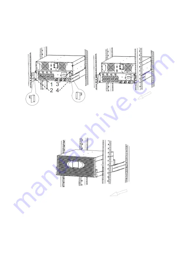
2.  Befestigen  Sie  die  PDU  mit  den  Hilfswinkeln  am  Rack  und 

trennen  Sie  diese  von  der  USV-Anlage.  Lösen  Sie  hierzu  4 
Schrauben (siehe Abbildung 38)


Abbildung 38: Ausbau XANTO S 10000, Schritt 2/3 


3.  Lösen Sie die 

19“ Montagewinkel der USV-Anlage an der Vor-

derseite  des  Racks  und  ziehen  Sie  die  USV-Anlage  aus  dem 
Rack (siehe Abbildung 39)


Abbildung 39: Ausbau XANTO S 10000, Schritt 3/3 


4.  Schrauben  Sie  die 

19“  Montagewinkel  von  der  USV-Anlage 

ab. 

5.  Der  Einbau  der  neuen  USV-Anlage  erfolgt  in  umgekehrter 

Reihenfolge. 


Summary of Contents for XANTO S 10000

Page 1: ...gina 145 216 Deutschland Italien Schweiz ONLINE USV Systeme AG Dreimühlenstraße 4 D 80469 München Phone 49 89 2423990 10 Fax 49 89 2423990 20 www online usv de ONLINE UPS Systems S r l Via Gilera Ferruccio 110 I 20862 Arcore MB Phone 39 039 2051444 Fax 39 039 2051435 ONLINE USV Systeme AG Eigenheimstraße 11 CH 8304 Wallisellen Zürich Phone 41 44 9452829 Fax 41 44 9453288 www online usv ch ...

Page 2: ...2 216 XS6000 XS10000_manual_ger_eng_it_V1 1 2 doc R Kistler ...

Page 3: ...lussvarianten 24 3 7 Inbetriebnahme 25 4 Betrieb 27 4 1 Funktionen auf dem Bedienfeld 27 4 2 Startbildschirm 28 4 3 Hauptmenü 29 4 3 1 Menü Einstellungen 30 4 4 Betriebszustände 32 4 5 Starten und Abschalten der USV Anlage 35 4 5 1 Starten der USV Anlage mit Versorgungsnetz 35 4 5 2 Starten der USV Anlage ohne Versorgungsnetz 35 4 5 3 Abschalten der USV Anlage mit Versorgungsnetz 36 4 5 4 Abschalt...

Page 4: ...n Batterien 51 7 2 Ausbau und Tausch von USV Anlagen 52 7 3 Lagerung von USV Anlagen Batterien 55 7 4 Zeitpunkt für das Austauschen der Batterien 55 7 5 Batterien wechseln 55 7 6 Testen der neuen Batterien 58 7 7 Entsorgen der Altbatterien oder der USV Anlage 58 8 Fehlerbehebung 59 8 1 Warn und Fehlermeldungen 60 8 2 Sonstige Fehlerursachen 63 8 3 Stummschalten des Alarmsignals 64 8 4 Support 64 9...

Page 5: ...nnt 24 Abbildung 15 Anschluss Frequenzumrichter ohne Bypass 24 Abbildung 16 Bedienfeld 27 Abbildung 17 Startbildschirm 28 Abbildung 18 Normalbetrieb 32 Abbildung 19 Batteriebetrieb 32 Abbildung 20 Bypassbetrieb 32 Abbildung 21 Standbybetrieb 33 Abbildung 22 Hocheffizienzbetrieb 33 Abbildung 23 Frequenzumrichterbetrieb 33 Abbildung 24 Warnmeldung 33 Abbildung 25 Fehlermeldung 34 Abbildung 26 Überla...

Page 6: ... fällt häufig dann aus wenn man es am we nigsten erwartet und die Qualität der Stromversorgung kann oft er heblichen Schwankungen unterliegen Netzprobleme können dazu führen dass kritische Daten zerstört werden ungesicherte Daten verloren gehen und Hardware beschädigt wird was zu teuren Repa raturen und Ausfallstunden führt Mit der XANTO S werden Ihre Anlagen vor Stromversorgungsprob lemen sicher ...

Page 7: ...ank Hocheffizienzbetrieb Rack Tower Kombimodell Höhe von nur 3HE bzw 5HE RS 232 und USB Schnittstelle Slot für optionalen SNMP Adapter AS400 oder Relais Karte Notaus Funktion REPO Remote Emergency Power Off Wartungsbypass Abbildung 1 XANTO S 6000 und 10000 Tower Installation Abbildung 2 XANTO S 6000 und 10000 Rack Installation ...

Page 8: ...pannung führen auch wenn die USV Anlage nicht an eine Wechselstromquel le angeschlossen ist Um Brandgefahr oder das Risiko eines elektrischen Schla ges zu verringern darf die USV Anlage nur in Gebäuden mit kontrollierter Temperatur und Luftfeuchtigkeit installiert wer den in denen keine leitenden Schmutzstoffe vorhanden sind Die Umgebungstemperatur darf 40 C nicht übersteigen Die USV Anlage darf n...

Page 9: ...rderlichen Vorsichtsmaßnahmen Die Wartung muss von qualifiziertem Personal durchgeführt wer den das im Umgang mit Batterien geübt ist und über gute Kenntnisse der erforderlichen Vorsichtsmaßnahmen verfügt siehe Wartung Halten Sie nicht autorisiertes Personal von Batterien fern Die Batterien müssen ordnungsgemäß entsorgt werden Hierbei sind die örtlichen Bestimmungen zu beachten Batterien dürfen ni...

Page 10: ...ann es zu Kondensatbildung innerhalb und außerhalb des Gehäuses kommen Installieren Sie die USV Anlage nur wenn Innen und Außenseite vollständig trocken sind Gefahr eines elektrischen Schlages Die USV Anlage hat ein hohes Gewicht siehe Technische Daten Zum Herausnehmen aus dem Karton und zur Mon tage werden mindestens zwei Personen benötigt HINWEIS Bewegen und öffnen Sie die verpackte USV Anlage v...

Page 11: ... 3 3 Überprüfung des Zubehörs Der Lieferumfang ist folgender Tabelle zu entnehmen USV Anlage Batteriepaket Beschreibung XANTO S 6000 XANTO S 10000 XANTO S 6000 XANTO S 10000 19 Montagewinkel 2 2 2 2 RS 232 Schnittstellenkabel 1 1 Parallelkabel 1 1 10A Kaltgeräteverlängerung 4 16A Kaltgeräteverlängerung 2 4 Bügel für Ausgangsanschlüsse 2 2 Gehäusestütze für Tower Montage 2 2 Hilfswinkel für PDU 1 2...

Page 12: ...ie USV Anlage auf eine ebene stabile Oberfläche an ihren endgültigen Platz siehe Abbildung 4 Abbildung 4 XANTO S 6000 und 10000 Tower Installation 2 Wenn Sie zusätzliche Batteriepakete installieren stellen Sie diese rechts neben die USV Anlage an ihre endgültigen Plät ze 3 Bei Installation ohne Batteriepaket montieren Sie bei der XANTO S 6000 die Gehäusestützen siehe Abbildung 4 4 Entfernen Sie di...

Page 13: ...an der oberen Seite XANTO S 10000 nur die linke Seite ACHTUNG Beim Anschließen der internen Batterien kann es zu einem kleinen Lichtbogen kommen Dies ist normal und kann nicht zur Gefährdung von Personen führen Verbinden Sie die Ka bel schnell und fest 7 Verbinden Sie die Steckverbindung für die internen Batterien Drücken Sie beide Teile fest zusammen um eine gute Verbin dung zu gewährleisten XANT...

Page 14: ... des Displays sie he Seite 13 5 4 Entfernen Sie bei dem rechten oder einzigen Batteriepaket den Kabelauswurf nur an der linke Seite der Frontblende 5 Falls Sie mehr als ein Batteriepaket installieren müssen bei jedem Batteriepaket beide Kabelauswürfe entfernt werden ACHTUNG Ein kleiner Lichtbogen kann auftreten wenn das Batteriepa ket an die USV Anlage angeschlossen wird Das ist normal und kann ni...

Page 15: ...Halterung an der unteren Seite des Ge häuses einrastet Drehen Sie die beiden Schrauben an der oberen Seite wieder fest Wiederholen Sie den Vorgang für jedes zusätzliche Batte riepaket und die USV Anlage 9 Fahren Sie mit dem Abschnitt Elektrische Installation fort XANTO S 10000 ACHTUNG Vor dem Anschließen der Batteriepakete an die USV Anlage sind die Batteriepakete zu erden 1 Schließen Sie jedes Ba...

Page 16: ...indungen zwischen den Batte riepaketen und der USV Anlage siehe Abbildung 6 Bis zu vier Batteriepakete können an die USV Anlage angeschlossen werden Abbildung 6 XANTO S 10000 mit BP Tower Rückansicht 3 Drehen des Frontblenden Einsatzes mit der Artikelbezeich nung des Batteriepaketes Verfahren Sie hier analog wie beim Drehen des Displays der USV Anlage siehe Seite 13 5 4 Einsetzen der Frontblenden ...

Page 17: ...Einbau ohne Batterien vorzu nehmen Zum Einsetzen der USV Anlage bzw des Batteriepaketes in das Rack werden mindestens zwei Personen benötigt Für die Rack Montage werden optionale Gleitschienen Art Nr Rack Kit HD angeboten Die Gleitschienen sind passend für 48 cm 19 Zoll Racks mit einer Bautiefe von 61 bis 76 cm 24 bis 30 Zoll HINWEIS Pro USV Anlage und pro Batteriepaket ist ein Rack Kit not wendig...

Page 18: ...der rechten Seite der Frontblende um die Frontblende zu entfernen Fassen Sie die Frontblende an zwei Seiten an schieben Sie sie nach rechts und entfernen Sie sie vom Gehäuse Abbildung 7 Frontblende der XANTO S 6000 und 10000 4 Entfernen Sie die Batterieabdeckung der Batterien siehe Abbildung 8 Abbildung 8 Batterieabdeckung der XANTO S 6000 und 10000 ACHTUNG Batterieeinschübe haben ein sehr hohes G...

Page 19: ...k Verwenden Sie hierfür auf beiden Seiten zwei M6 x 16 Flachkopfschrauben und zwei M6 Käfig muttern Wiederholen Sie den Vorgang für alle weiteren Batteriepakete ACHTUNG Batterieeinschübe haben ein sehr hohes Gewicht 10 Schieben Sie die Batterieeinschübe wieder in die USV Anlage die Batteriepakete ACHTUNG Beim Anschließen der internen Batterien der USV Anlage kann es zu einem kleinen Lichtbogen kom...

Page 20: ...der Frontblende der USV Anlage HINWEIS Gehen Sie vorsichtig vor um das LCD Anzeige und Bedien feld und das angeschlossene Flachbandkabel nicht zu be schädigen 2 Entfernen Sie bei dem unteren oder einzigen Batteriepaket den Kabelauswurf nur an der oberen Seite der Frontblende 3 Falls Sie mehr als ein Batteriepaket installieren müssen bei jedem Batteriepaket beide Kabelauswürfe entfernt werden ACHTU...

Page 21: ...nzusetzen stellen Sie sicher dass die Kabel des Batteriepaketes durch die Kabelauswürfe geführt sind Schieben Sie anschließend die Frontblende nach links bis sie in die Halterung an der linke Seite des Gehäuses einrastet Drehen Sie die beiden Schrauben an der rechten Seite der Frontblende wieder fest Wiederholen Sie den Vorgang für jedes zusätzliche Batte riepaket und die USV Anlage 7 Fahren Sie m...

Page 22: ... in die Batterie Steckverbindung der USV Anlage ein 2 Verbinden Sie alle Steckverbindungen zwischen den Batte riepaketen und der USV Anlage siehe Abbildung 11 Bis zu vier Batteriepakete können an die USV Anlage angeschlossen werden Abbildung 11 XANTO S 10000 mit BP Rackeinbau Rückansicht 3 Einsetzen der Frontblenden Schieben Sie die Frontblenden nach links bis sie in die Halte rung an der linken S...

Page 23: ... durch eine Elektrofachkraft erfolgen 3 6 1 Kabelquerschnitte und Sicherungen XANTO S 6000 XANTO S 10000 Eingang 4mm 2 6mm 2 Ausgang Klemme 4mm 2 6mm 2 Sep Erdungsleiter nur bei Rackeinbau 4mm 2 6mm 2 Leistungsschutzschalter 2 polig in Zuleitung nicht im Lieferumfang 32A 50A Auslösecharakteristik C Sicherung im Batteriepaket 60A 80A Tabelle 2 Kabelquerschnitt mehradrig und Sicherungen 3 6 2 Klemml...

Page 24: ...er Anschluss Eingang und Bypass USV Anlage mit getrenntem Normal und Bypass Anschluss Abbildung 14 Getrennter Anschluss Eingang und Bypass getrennt USV Anlage als Frequenzumrichter ohne Bypass Abbildung 15 Anschluss Frequenzumrichter ohne Bypass Fahren Sie mit dem Abschnitt Inbetriebnahme fort Eingang Ausgang Eingang Ausgang Bypass Eingang Ausgang Brücke einlegen Keine Brücke ...

Page 25: ...gt kurz das ONLINE Logo an 4 Überprüfen Sie ob sich die USV Anlage im Bypassbetrieb be findet siehe Betriebszustände 5 Drücken Sie die Taste an der USV Anlage mindestens eine Sekunde lang Ein akustisches Signal ertönt Ein paar Sekun den später schaltet die USV Anlage in den Normalbetrieb 6 Falls das Display der USV Anlage aktive Warn Fehlermel dungen anzeigt beheben Sie diese bevor Sie mit der Inb...

Page 26: ... Statuswechsel auf dem Display der USV Anlage Deaktivieren Sie den Notaus Schalter und starten Sie die USV Anlage neu HINWEIS Die internen Batterien lassen sich in weniger als drei Stun den auf 90 ihrer Kapazität aufladen ONLINE empfiehlt die Batterien nach der Installation oder nach längerer Lagerung 48 Stunden lang aufzuladen Wenn zusätzliche Batteriepake te installiert wurden lesen Sie die Lade...

Page 27: ... ist mit dem Versorgungsnetz verbunden und befindet sich im Bypassbetrieb Taste länger als 1s drücken Wechsel in Bypassbetrieb Die USV Anlage ist mit dem Versorgungsnetz verbunden und befindet sich im Normalbetrieb Taste länger als 3s drücken Ausschalten Die USV Anlage ist nicht mit dem Versorgungs netz verbunden und befindet sich im Batteriebe trieb Taste länger als 3s drücken Hauptmenü aufrufen ...

Page 28: ...r Inaktivität z B bei Einstellungen zeigt das LCD den Startbildschirm an Abbildung 17 Startbildschirm USV Eingang Abwechselnd werden der Netzeingang Netz und der Bypasseingang Bypass mit Spannung und Frequenz angezeigt USV Betriebszustand Es wird der jeweilige Betriebszustand angezeigt z B Normalbetrieb siehe Betriebszustände Batterie Die Batterie wird als Balken dargestellt Bei vollgeladenen Batt...

Page 29: ...ntrolle Alarm lautlos Schaltet den akustischen Alarm aus Einzel USV aus Schaltet eine einzelne USV Anlage die im Pa rallelbetrieb läuft in den Standbybetrieb Batterietest Startet einen manuellen Batterietest im Einzel betrieb siehe Testen der neuen Batterien Batterietest parallel Startet einen manuellen Batterietest im Paral lelbetrieb siehe Testen der neuen Batterien REPO Status löschen Löscht de...

Page 30: ...USER Empfehlung nicht ändern Deaktiviert Akustischer Alarm Aktiviert Deaktiviert Empfehlung nicht ändern Aktiviert Ausgangs spannung 208V 220V 230V 240V Empfehlung nicht ändern 230V Ausgangsfrequenz 50Hz 60Hz autom Erkennung Empfehlung nicht ändern autom Erkennung Energiestrategie Normal Hocheffizienz Frequenzumrichter Im Modus Frequenzumrichter muss die Aus gangsfrequenz fest eingestellt werden E...

Page 31: ...ndern 184V Bypassspannung oberes Limit 245V 276V Empfehlung nicht ändern 264V Bypassfrequenz unteres Limit 1 20 Empfehlung nicht ändern 10 Bypassfrequenz oberes Limit 1 40 Empfehlung nicht ändern 10 Hocheff spg unteres Limit 5 10 Empfehlung nicht ändern 5 Hocheff spg oberes Limit 5 10 Empfehlung nicht ändern 5 Hocheff freq unteres Limit 1 10 Empfehlung nicht ändern 5 Hocheff freq oberes Limit 1 10...

Page 32: ...le vier Sekunden bei niedriger Batterie kapazität jede Sekunde Nach Rückkehr des Versorgungsnet zes wechselt die USV Anlage in den Normalbetrieb und die Batterien wer den wieder geladen Bypassbetrieb Abbildung 20 Bypassbetrieb Die USV Anlage läuft im Bypassbe trieb Ein akustisches Warnsignal er tönt alle zwei Minuten Der Batteriebetrieb ist nicht verfügbar und die Verbraucher sind nicht vor Stroma...

Page 33: ...t wird mit Strom versorgt Hocheffizienzbetrieb Die USV Anlage läuft im Hocheffi zienzbetrieb Der Hocheffizienzbetrieb kann manu ell über das Bedienfeld oder die Soft ware aktiviert werden Abbildung 22 Hocheffizienzbetrieb Frequenzumrichterbetrieb Die USV Anlage läuft im Frequenz umrichterbetrieb Der Frequenzumrichterbetrieb kann manuell über das Bedienfeld oder die Software aktiviert werden Abbild...

Page 34: ...Sie sich an den Support Abbildung 25 Fehlermeldung Überlast Abbildung 26 Überlast Die USV Anlage zeigt eine Überlast an siehe Technische Daten Zwei akustische Signale ertönen je Sekun de Verringern Sie umgehend die ange schlossene Last Batterietest Abbildung 27 Batterietest Die USV Anlage führt einen Batterie test durch Batteriewarnung Abbildung 28 Batteriewarnung Die USV Anlage zeigt defekte oder...

Page 35: ...SV Anlage mindestens eine Sekunde lang Ein akustisches Signal ertönt Ein paar Sekun den später schaltet die USV Anlage in den Normalbetrieb Bei gestörtem Versorgungsnetz schaltet die USV Anlage in den Batteriebetrieb 4 5 2 Starten der USV Anlage ohne Versorgungsnetz HINWEIS Das Starten im Batteriebetrieb kann deaktiviert werden sie he Menü Einstellungen Kaltstart 1 Drücken Sie kurz die Taste an de...

Page 36: ... Anlage ab 3 Nach kurzer Zeit schaltet die USV Anlage ab 4 5 4 Abschalten der USV Anlage ohne Versorgungsnetz 1 Drücken Sie die Taste an der USV Anlage drei Sekunden lang Ein akustisches Signal von drei Sekunden Dauer ertönt Die USV Anlage wechselt in den Standbybetrieb HINWEIS Wird die Taste nach weniger als drei Sekunden losgelas sen so bleibt die USV Anlage im Normalbetrieb 2 Nach kurzer Zeit s...

Page 37: ...te kurz um zum Startbildschirm zurück zu kehren Die folgenden Einstellungen sind zusätzlich für die Konfiguration des Hocheffizienzbetriebs verfügbar Hocheff spg unteres Limit Standardmäßig ist ein Wechsel in den Bypassbetrieb deaktiviert wenn die gemessene Bypassspannung 5 unter der Nennspannung liegt Sie können die Einstellung für ei nen anderen Prozentwert festlegen Hocheff spg oberes Limit Sta...

Page 38: ...ebs verfügbar Bypassspannung unteres Limit Standardmäßig ist ein Wechsel in den Bypassbetrieb deaktiviert wenn die gemessene Bypassspan nung unter 184V liegt Sie können die Einstellung für einen anderen Spannungswert festlegen Bypassspannung oberes Limit Standardmäßig ist ein Wechsel in den Bypassbetrieb deaktiviert wenn die gemessene Bypassspan nung über 264V liegt Sie können die Einstellung für ...

Page 39: ...andardeinstellung Nur USV Anlage interne Batterien 1 USV Anlage 1 Batteriepaket 2 USV Anlage 2 Batteriepakete 3 USV Anlage 3 Batteriepakete 4 USV Anlage 4 Batteriepakete Tabelle 7 Externe Batteriepakete 3 Drücken Sie die Taste zur Bestätigung mindestens eine Sekunde lang 4 Drücken Sie die Taste kurz um zum Startbildschirm zurück zu kehren 4 8 2 Automatische Batterietests Automatische Batterietests...

Page 40: ...atische Neustarts Nach Abschaltung der USV Anlage z B durch leere Batterien bei Stromausfall wird die USV Anlage standardmäßig neu gestartet sobald die Stromversorgung wieder hergestellt ist Sie können die Einstellung deaktivieren 1 Drücken Sie die Taste mindestens eine Sekunde lang um die Menüoptionen zu aktivieren Wählen Sie EINSTEL LUNGEN und anschließend AUTOMATISCHER NEU START aus 2 Wählen Si...

Page 41: ...USV Status Menü bei Statusinformation signalisiert Parallelbetrieb Diese Betriebsart ermöglicht die Erweiterung des Leistungsberei ches eine Redundanz ist hier nicht gegeben So kann z B an eine XANTO S 6000 nachträglich eine weitere XANTO S 6000 ange schlossen werden um die Gesamtleistung auf 12000VA zu erhöhen 5 1 1 Elektrische Installation Redundanz Parallelbetrieb HINWEIS Es können maximal zwei...

Page 42: ...Achten Sie darauf dass alle Leis tungsschalter geöffnet sind 3 Außerdem empfiehlt ONLINE einen zusätzlichen Wartungs Bypass nicht im Lieferumfang für den Verbund zu installieren siehe Abbildung 30 4 Legen Sie bei jeder USV Anlage die Brücke zwischen L2 und JP ein siehe Abbildung 29 5 Die angeschlossenen Kabel für Eingang und Ausgang müssen mindestens den Kabelquerschnitten aus Tabelle 2 entspre ch...

Page 43: ...ass für Redundanz Parallelbetrieb Maintenance Bypass for redundancy parallel mode Verbraucher Load Ausgangs Schalter Output Breaker USV 1 UPS 1 Ausgangs Schalter Output Breaker Haupt Ausgangs Schalter Main Output Breaker USV 2 UPS 2 Eingangs Schalter Input Breaker Eingangs Schalter Input Breaker Abbildung 30 Anschlussplan 2 Parallelschaltung ...

Page 44: ...h tet auf und zeigt das ONLINE Logo an 4 Überprüfen Sie ob sich die USV Anlagen im Bypassbetrieb befinden siehe Betriebszustände 5 Drücken Sie die Taste an einer USV Anlage mindestens eine Sekunde lang Alle USV Anlagen wechseln in den Nor malbetrieb 6 Falls das Display einer USV Anlage aktive Warn Fehlermel dungen anzeigt beheben Sie die Probleme bevor Sie mit der Inbetriebnahme fortfahren siehe F...

Page 45: ...t definierten Ausgangsfrequenz 50Hz oder 60Hz egal wel che Eingangsfrequenz 40Hz bis 70Hz anliegt Eine feste Aus gangsfrequenz ist z B für empfindliche Verbraucher erforderlich 1 Drücken Sie die Taste mindestens eine Sekunde lang um die Menüoptionen zu aktivieren Wählen Sie EINSTEL LUNGEN und anschließend ENERGIESTRATEGIE aus 2 Wählen Sie FREQUENZUMRICHTER und drücken Sie die Taste zur Bestätigung...

Page 46: ...K O M M U N I K A T I O N 46 216 XS6000 XS10000_manual_ger_eng_it_V1 1 2 doc R Kistler 6 Kommunikation Abbildung 31 Kommunikationsoptionen XANTO S 6000 Abbildung 32 Kommunikationsoptionen XANTO S 10000 ...

Page 47: ...SV Anlage an In Abbildung 31 und Abbildung 32 ist die Position der Kommunikationsschnittstellen dargestellt HINWEIS Die RS 232 und USB Kommunikationsschnittstelle kann nicht gleichzeitig verwendet werden Wenn das Verbindungskabel angeschlossen ist kann die DataWatch Software mit der USV Anlage Daten austauschen siehe DataWatch Software Die Software ruft bei der USV Anlage detaillierte Anga ben zum...

Page 48: ...eibung DW7SNMP30 SNMP Adapter Basic Der SNMP Adapter kommuniziert via TCP IP mit den ange schlossenen Verbrauchern im Netzwerk DW5SNMP30 SNMP Adapter Professional Funktion wie Basic jedoch mit zusätzlicher Schnittstelle für Tem peraturfühler und Gebäudemanagement PHXNOV I Relais Einschubkarte Meldung von Batteriebetrieb Normalbetrieb und Batteriekapazität niedrig Signaleingang zur USV Abschaltung ...

Page 49: ...r darf nicht an Schaltkreise angeschlos sen werden die mit dem Versorgungsnetz verbunden sind Eine verstärkte Isolierung zum Netz ist erforderlich Der Notaus Schalter muss mindestens für 24V und 20mA ausge legt sein Es muss ein Öffner verwendet werden Für den ordnungsgemäßen Betrieb muss die Notaus Funktion min destens 250ms lang aktiv bleiben Wenn die die Notaus Funktion aktiviert wird muss zusät...

Page 50: ...ste aller Funktionen Automatische Datensicherung mit dem Schließen laufender Anwendungen und dem geordneten Herunter fahren des gesamten Systems mittels frei konfigurierbarer Shut downroutine Darüber hinaus verfügt DataWatch über ein umfangrei ches Messaging System zeitgesteuerte Testroutinen sowie eine Er eignisprotokollierung DataWatch unterstützt alle aktuellen Betriebssysteme Als Client Server...

Page 51: ...ubsauger Um eine lange Lebensdauer der Batterien zu erreichen sollte die Umgebungstemperatur unter 25 C betragen HINWEIS Die Batterien in der USV Anlage sind für eine Lebensdauer von drei bis fünf Jahren ausgelegt Die Lebensdauer einer Batterie variiert je nach Nutzungshäufigkeit und Umgebungs temperatur Nach Ablauf der zu erwartenden Lebensdauer haben weiter verwendete Batterien häufig deutlich v...

Page 52: ... Tau schen der USV Anlage müssen die Verbraucher nicht abgeschaltet werden XANTO S 6000 1 Entfernen Sie die Sicherungsabdeckung vom Wartungsby pass lösen Sie hierzu 2 Schrauben Schalten Sie den War tungsbypass auf Bypass siehe Abbildung 34 Abbildung 34 Ausbau XANTO S 6000 Schritt 1 3 2 Schrauben Sie den Hilfswinkel an die PDU und trennen Sie diese von der USV Anlage Lösen Sie hierzu 3 Schrauben Sc...

Page 53: ... Abbildung 36 Abbildung 36 Ausbau XANTO S 6000 Schritt 3 3 4 Schrauben Sie die 19 Montagewinkel von der USV Anlage ab 5 Der Einbau der neuen USV Anlage erfolgt in umgekehrter Reihenfolge XANTO S 10000 1 Entfernen Sie Sicherungsabdeckung vom Wartungsbypass entfernen Lösen Sie hierzu 2 Schrauben Schalten Sie den Wartungsbypass auf Bypass siehe Abbildung 37 Abbildung 37 Ausbau XANTO S 10000 Schritt 1...

Page 54: ... Schrauben siehe Abbildung 38 Abbildung 38 Ausbau XANTO S 10000 Schritt 2 3 3 Lösen Sie die 19 Montagewinkel der USV Anlage an der Vor derseite des Racks und ziehen Sie die USV Anlage aus dem Rack siehe Abbildung 39 Abbildung 39 Ausbau XANTO S 10000 Schritt 3 3 4 Schrauben Sie die 19 Montagewinkel von der USV Anlage ab 5 Der Einbau der neuen USV Anlage erfolgt in umgekehrter Reihenfolge ...

Page 55: ...iten im Abschnitt Technische Daten nach 7 4 Zeitpunkt für das Austauschen der Batterien Wenn das Alarmsignal zu hören ist und der Hinweis Batteriewar tung erforderlich aufleuchtet müssen die Batterien ausgetauscht werden Wenden Sie sich an Ihren Händler oder ONLINE um neue Batterien zu bestellen 7 5 Batterien wechseln HINWEIS Entfernen Sie die Batterien nicht solange die USV Anlage im Batteriebetr...

Page 56: ...kzeuge oder Metallteile nicht auf den Batterien ab Die Batterien dürfen nur gegen die gleiche Anzahl typglei cher Batterien ausgetauscht werden Batterien müssen sachgemäß entsorgt werden Richten Sie sich bei der Entsorgung nach den örtlich geltenden gesetzli chen Bestimmungen Batterien dürfen nicht verbrannt werden Es besteht Explosi onsgefahr Sehen Sie vom Öffnen oder Herumhantieren mit den Batte...

Page 57: ... aufweisen wie die Altbatterien 5 Tauschen Sie die Batterien im Batterieeinschub aus Lesen Sie den Abschnitt Entsorgen der Altbatterien oder der USV Anlage für eine sachgemäße Entsorgung 6 Schieben Sie den Batterieeinschub mit den neuen Batterien in das Gehäuse Es muss dabei Druck ausgeübt werden 7 Setzen Sie die Batterieabdeckung wieder ein ACHTUNG Ein kleiner Lichtbogen kann auftreten wenn die B...

Page 58: ...des ursprünglichen Zu stands Auf dem Display wird der Betriebszustand BATTERIETEST angezeigt Das Ergebnis wird anschließend auf der Statusanzeige dargestellt 7 7 Entsorgen der Altbatterien oder der USV Anlage Erkundigen Sie sich vor Ort bei einer Recycling Stelle oder einer Sondermüllanlage wie die Altbatterie oder die USV Anlage ord nungsgemäß entsorgt werden Altbatterien können auch kostenlos be...

Page 59: ...he Betriebszustände Aktive Warn Fehlermeldungen werden zusätzlich durch ein akustisches Alarmsignal gemeldet siehe Betriebszustände Beheben Sie die Ursache bzw wenden Sie sich an den Support Statusmenü auf eine Liste aktiver Warn Fehlermeldungen überprü fen 1 Drücken Sie die Taste mindestens eine Sekunde lang um die Menüoptionen zu aktivieren 2 Drücken Sie die Taste bis USV STATUS angezeigt wird 3...

Page 60: ...ft im Batteriebetrieb und der Batterieladestand ist niedrig Die USV Anlage versorgt die an geschlossene Last nur noch kurz mit Batteriestrom Bereiten Sie die ange schlossene Last auf das unmittelbare Herunterfahren vor 13 Warnung BATT ersetzen Fehlerhafte Batterien wurden erkannt und das Ladegerät deaktiviert Tauschen Sie die fehlerhaften Batte rien aus oder wenden Sie sich an den Support 14 Warnu...

Page 61: ...Notaus Anschluss 72 Warnung Wartungsbypass ein Der Wartungsbypass wurde aktiviert Überprüfen Sie den Wartungsbypass an der Rückseite der USV Anlage 81 Fehler USV Übertemperatur Die innere Temperatur der USV Anlage ist zu hoch Schalten Sie die USV Anlage in den Bypassbetrieb Falls die Temperatur nicht fällt USV Anlage ausschalten und abkühlen lassen Sorgen Sie für ausreichende Luftzirkulation oder ...

Page 62: ...ie defekt E7 Warnung Eingangsspannung asym Unterschiedliche Eingangsspannungen Überprüfen Sie die Eingangsspan nungen jeder USV Anlage E8 Warnung Bypasseingang asym Unterschiedliche Bypassspannungen Überprüfen Sie die Bypassspannun gen jeder USV Anlage E9 Warnung Ausgangsleistung asym Unterschiedliche USV Anlagen parallel ge schaltet Schalten Sie nur gleiche USV Anlagen zusammen EA Warnung Energie...

Page 63: ...t richtig angeschlossen Prüfen Sie die Anschlüsse des Netz kabels Der Notausschalter ist aktiv oder der REPO Anschluss fehlt Überprüfen Sie den Notaus Anschluss Die USV Anlage läuft im Normalbe trieb aber einige oder alle Verbrau cher sind nicht ein geschaltet Die Verbraucher sind nicht richtig an die USV Anlage angeschlossen Überprüfen Sie ob die Verbraucher mit den Anschlüssen der USV Anlage ver...

Page 64: ...l wieder ausgegeben Dieses hat Vorrang gegenüber der vorherigen Stummschaltung des Alarmsignals 8 4 Support Als deutscher Anbieter garantiert ONLINE direkte Ansprechbarkeit unbürokratische Bearbeitung und kürzeste Reaktionszeiten Umfas sende Unterstützung ist selbstverständlich vor und nach dem Kauf Bei ONLINE werden umfassende Support und Serviceleistungen großgeschrieben Direkte Beratung und Sup...

Page 65: ... 700 mm 46 kg XANTO S 10000 215 5 5U x 438 x 710 mm 83 kg Batteriepaket XANTO S 6000 129 3U x 438 x 600 mm 44 kg Batteriepaket XANTO S 10000 129 3U x 438 x 600 mm 63 kg Tabelle 13 Abmessungen und Gewicht 9 1 3 Elektrische Ein und Ausgänge Nennfrequenz 50 60Hz automatische Erfassung Frequenzbereich 40 70Hz vor Wechsel in Batteriebetrieb Bypass Spannungsbereich 15 20 der Nennspannung Standard Übersp...

Page 66: ...Ausgangsleistung Normalbetrieb 1 100 102 Aktiviert Überlastungs Hinweis 2 102 129 Last wechselt nach 2Min in den Bypassbetrieb 3 130 149 Last wechselt nach 30s in den Bypassbetrieb 4 150 Last wechselt nach 100ms in den Bypassbetrieb HINWEIS Bei Standardkonfiguration wechselt die Anlage bei 102 sofort in den Bypassbetrieb Überlastung Ausgangsleistung Bypassbetrieb 1 130 Bypassbetrieb aktiv 2 130 US...

Page 67: ...er 3 5 Jahre gemäß EUROBAT Aufladezeit 90 Interne Batterien 3 Stunden 1 BP 6 Stunden 2 BPs 9 Stunden 3 BPs 12 Stunden 4 BPs 15 Stunden Tabelle 19 Batterie 9 1 5 Überbrückungszeit Gerätetyp Interne Batterie 1 BP 2 BP 3 BP 4 BP XANTO S 6000 13 6 30 13 53 22 79 33 107 45 XANTO S 10000 13 6 31 13 52 22 74 31 97 41 Tabelle 20 Überbrückungszeit in Minuten bei 50 100 Last pf 0 7 9 1 6 Kommunikationsoptio...

Page 68: ...EN 61000 4 8 Ebene 3 EMV Zertifikate CE gemäß IEC EN 62040 2 Sicherheit EN 62040 1 2008 Zulassung CE Schutzart IP20 Betriebstemperatur 0 C bis 40 C Lagertemperatur 0 C bis 40 C mit Batterien 25 C bis 55 C ohne Batterien Relative Luftfeuchtigkeit 0 95 nicht kondensierend Betriebshöhe Bis zu 1000 Meter über NN 100 Ausgangsleistung Leistungsminderung von 1 je weitere 100m Hörbares Geräusch 55dBA bei ...

Page 69: ...T E N 69 216 XS6000 XS10000_manual_ger_eng_it_V1 1 2 doc R Kistler 9 2 Rückansichten der USV Anlagen Beschreibung der Anschlüsse siehe Abbildung 31 und Abbildung 32 Kommunikation Abbildung 40 XANTO S 6000 und 10000 Rückansicht ...

Page 70: ...T E C H N I S C H E D A T E N 70 216 XS6000 XS10000_manual_ger_eng_it_V1 1 2 doc R Kistler 9 3 CE Bestätigung ...

Page 71: ...den Von hierin vorgesehenen Ausnahmen abgesehen übernimmt ONLINE keinerlei ausdrückliche oder stillschweigende Garantie ein schließlich der Zusicherung handelsüblicher Qualität oder der Eig nung für einen bestimmten Zweck In einigen Gerichtsbarkeiten ist die Einschränkung oder der Ausschluss stillschweigender Garantien untersagt so dass die vorstehenden Einschränkungen oder Aus schlüsse für den Kä...

Page 72: ...72 216 XS6000 XS10000_manual_ger_eng_it_V1 1 2 doc R Kistler ...

Page 73: ...216 Germany Italy Switzerland ONLINE USV Systeme AG Dreimühlenstraße 4 D 80469 Munich Phone 49 89 2423990 10 Fax 49 89 2423990 20 www online usv de ONLINE UPS Systems S r l Via Gilera Ferruccio 110 I 20862 Arcore MB Phone 39 039 2051444 Fax 39 039 2051435 www online ups it ONLINE USV Systeme AG Eigenheimstraße 11 CH 8304 Wallisellen Zurich Phone 41 44 9452829 Fax 41 44 9453288 www online usv de ...

Page 74: ...74 216 XS6000 XS10000_manual_ger_eng_it_V1 1 2 doc R Kistler ...

Page 75: ...tion variants 96 3 7 Commissioning 97 4 Operation 99 4 1 Functions on the control panel 99 4 2 Start screen 100 4 3 Main menu 101 4 3 1 Settings menu 102 4 4 Operating states 104 4 5 Starting and switching off the UPS system 107 4 5 1 Starting the UPS system with mains power supply 107 4 5 2 Starting the UPS system without mains power supply 107 4 5 3 Switching off the UPS system with mains power ...

Page 76: ... UPS systems batteries 123 7 2 Removing and replacing UPS systems 124 7 3 Storing UPS systems batteries 127 7 4 When to replace batteries 127 7 5 Replacing batteries 127 7 6 Testing the new batteries 130 7 7 Disposing of old batteries or the UPS system 130 8 Troubleshooting 131 8 1 Warning and error messages 132 8 2 Other folds causes 135 8 3 Muting the alarm signal 136 8 4 Support 136 9 Technical...

Page 77: ...put and bypass separated 96 Figure 15 Connection converter without bypass 96 Figure 16 Control panel 99 Figure 17 Start screen 100 Figure 18 Normal mode 104 Figure 19 Battery mode 104 Figure 20 Bypass mode 104 Figure 21 Standby mode 105 Figure 22 HE mode 105 Figure 23 Converter mode 105 Figure 24 Warning message 105 Figure 25 Error message 106 Figure 26 Overload 106 Figure 27 Battery test 106 Figu...

Page 78: ...upply often fails when you least expect it and the quality of the power supply can often be subject to significant fluctua tions Network problems can lead to critical data being destroyed unsecured data being lost and hardware damaged which leads to expensive repairs and downtimes With the XANTO S your systems are securely protected against power supply problems and the functionality of the hardwa...

Page 79: ...ack tower combination model height of only 3 HU resp 5 HU Height Unit RS 232 and USB interfaces Slot for optional SNMP adapter AS400 card or relay card Emergency off function REPO Remote Emergency Power Off Maintenance Switch Figure 1 XANTO S 6000 and 10000 Tower Installation Figure 2 XANTO S 6000 and 10000 Rack Installation ...

Page 80: ...upply batteries The output of the UPS system can conduct voltage even when the UPS system is not connected to an AC power source To reduce the risk of fire or an electric shock the UPS system may only be installed in buildings with controlled temperature and air humidity in which there are no conduct ing contaminants present The ambient temperature may not rise above 40 C The UPS system may not be...

Page 81: ...cessary measures The maintenance must be performed by qualified personnel who have been trained in the handling of batteries and who have sound knowledge about the required safety measures see Maintenance Keep unauthorised personnel away from batteries The batteries must be disposed of properly Observe the local regulations for proper disposal Batteries may not be incinerated There is a risk of ex...

Page 82: ...bient tempera tures condensation may form on the outside and inside of the housing Install the UPS system only when the inside and outside are completely dry risk of an electric shock The UPS system is heavy see Technical Data At least two persons are required for lifting out of the packaging and for the installation NOTE Move and open the packaged UPS system carefully Leave the components in the ...

Page 83: ...accessories Refer to the following table for the scope of supply UPS system Battery module Description XANTO S 6000 XANTO S 10000 XANTO S 6000 XANTO S 10000 19 mounting bracket 2 2 2 2 RS 232 interface cable 1 1 Parallel cable 1 1 10A low heat devices power cord 4 16A low heat devices power cord 2 4 Bracket for output connections 2 2 Housing bracket for tower installation 2 2 Support bracket for P...

Page 84: ...le 1 Place the UPS system on a level stable surface at its final position see Figure 4 Figure 4 XANTO S 6000 and 10000 Tower Installation 2 If you are installing additional battery modules position these to the right next to the UPS system at its final position 3 For installation without battery modules mount the housing brackets for the XANTO S 6000 see Figure 4 4 Remove the front cover of the UP...

Page 85: ...ry cover unscrew the two screws on the upper side XANTO S 10000 only the left side CAUTION When connecting the internal batteries a small spark may occur This is normal and does not pose a hazard to people Connect the cables quickly and firmly 7 Connect the plug connection again for the internal batteries Press both parts together firmly to ensure a good connection XANTO S 10000 only the left side...

Page 86: ...gue to the turning of the display see page 87 5 4 For the right or only battery module remove the cable ejec tion on the left side of the front cover only 5 If you are installing more than one battery module both cable ejections must be removed for every battery module CAUTION A small spark can occur when the battery module is con nected to the UPS system This is normal and does not pose a hazard ...

Page 87: ...until it engages in the holder on the underside of the housing Retighten the two screws on the upper side Repeat the procedure for each additional battery module and the UPS system 9 Proceed with section Electrical installation XANTO S 10000 CAUTION Before connecting the battery modules to the UPS system the battery modules must be grounded 1 Connect each battery module to the ground connection sc...

Page 88: ...system 2 Connect all plug connections between the battery modules and the UPS system see Figure 6 Up to four batteries can be connected to the UPS system Figure 6 XANTO S 10000 with BP Tower rear view 3 Turn the front cover insert with the article description of the battery module Proceed here analogue to the turning of the display see page 87 5 4 Inserting the front covers Slide the front cover d...

Page 89: ... without batteries At least two persons are required for inserting the UPS sys tem or the battery module into the rack Optional slide rails article number Rack Kit HD are available for rack installation The slide rails are appropriate for 48 cm 19 inch racks with an installation depth of 61 to 76 cm 24 to 30 inch NOTE One rack kit is required per UPS system and per battery module Mount the battery...

Page 90: ... Figure 7 Unscrew the two screws on the right side of the front cover to remove the front cover Grasp the front cover on two sides slide it to the right and remove it from the housing Figure 7 Front cover of the XANTO S 6000 and 10000 4 Remove the battery cover of the batteries see Figure 8 Figure 8 Battery cover of the XANTO S 6000 and 10000 CAUTION Battery module inserts are very heavy 5 Pull th...

Page 91: ...ure the UPS system battery module with the housing bracket to the rack Use two M6 x 16 pan head screws and two M6 cage nuts Repeat the procedure for all additional battery modules CAUTION Battery modules are very heavy 10 Push the battery module inserts into the UPS systems battery modules again CAUTION When connecting the internal batteries a small spark may occur This is normal and does not pose...

Page 92: ... of the front cover of the UPS system NOTE Proceed carefully so that you do not damage the LCD display and control panel and the connected ribbon cable 2 For the lower or only battery module remove the cable ejec tion on the upper side of the front cover only 3 If you are installing more than one battery module both cable ejections must be removed for every battery module CAUTION A small spark can...

Page 93: ...the battery module To insert the front cover again make sure that the cables of the battery module are guided through the cable ejections Then slide the front cover to the left until it engages in the holder on the left side of the housing Retighten the two screws on the right side of the front cover Repeat the procedure for each additional battery module 7 Proceed with section Electrical installa...

Page 94: ...t the cable of the battery module into the battery plug connection of the UPS system 2 Connect all plug connections between the battery modules and the UPS system see Figure 11 Up to four batteries can be connected to the UPS system Figure 11 XANTO S 10000 with BP Rack Installation rear view 3 Inserting the front covers Slide the front cover to the left until it engages in the holder on the left s...

Page 95: ...nnect the UPS system to the power supply 3 6 1 Cable cross sections and fuses XANTO S 6000 XANTO S 10000 Line input 4mm 2 6mm 2 Output Terminal 4mm 2 6mm 2 Separate ground conductor only rack 4mm 2 6mm 2 Circuit breaker 2 pole in the feedline not included 32A 50A Trigger characteristic C Fuse in the battery module 60A 80A Table 2 Cable cross section multicore and fuses 3 6 2 Terminal strip Please ...

Page 96: ...igure 13 Common connection line input and bypass UPS system with separate normal and bypass connection Figure 14 Separate connection line input and bypass separated UPS system as converter without bypass Figure 15 Connection converter without bypass Proceed with section Commissioning Line input Output Line input Output Bypass Line input Output Insert jumper No jumper ...

Page 97: ...ights up and displays the ONLINE logo 4 Check whether the UPS system is in the bypass mode see Operating states 5 Press the button on the UPS system for at least one sec ond An audio signal will be emitted Several seconds later the UPS system will switch to normal mode 6 If the display of the UPS system displays active warning error messages rectify these before you proceed with commission ing the...

Page 98: ...d check that the status switches on the display of the UPS system Deactivate the emergency off switch and restart the UPS system NOTE The internal batteries will charge up to 90 of their capacity in less than three hours ONLINE recommends charging the batteries for 48 hours after installation or after a longer peri od of storage If additional battery modules were installed please refer to the char...

Page 99: ... is connected to the mains power supply and is in bypass mode Press the button longer than 1 second Switch to bypass mode The UPS system is connected to the mains power supply and is in normal mode Press the button longer than 3 seconds Switch off The UPS system is not connected to the mains power supply and is in battery mode Press the button longer than 3 seconds Call up the main menu The UPS sy...

Page 100: ... of inactivity e g for settings the start screen will be displayed on the LCD Figure 17 Start screen UPS line input The mains input line and the bypass input by pass are shown alternating with voltage and frequency UPS operating state The respective operating state is displayed e g normal mode see Operating states Battery The battery is displayed as bars For fully charged batteries the bar appears...

Page 101: ...udio alarm Single UPS turn off Switches an individual UPS system which is running in increase mode into standby mode Start Battery Test Starts a manual battery test in individual mode see Testing the new batteries Start Battery Test Parallel Starts a manual battery test in increase mode see Testing the new batteries Clear REPO Sta tus Deletes the REPO status Reset Fault Sta tus Deletes the error l...

Page 102: ...ssword is USER Recommendation Do not change Disabled Audio Alarms Enabled Disabled Recommendation Do not change Enabled Output Voltage 208V 220V 230V 240V Recommendation Do not change 230V Output Frequency 50Hz 60Hz Autosensing Recommendation Do not change Autosensing Power Strategy Normal High Efficiency Converter In the Converter mode the Output Frequen cy must be set Recommendation Adapt to req...

Page 103: ... 120V 215V Recommendation Do not change 184V Bypass Voltage High Limit 245V 276V Recommendation Do not change 264V Bypass Frequency Low Limit 1 20 Recommendation Do not change 10 Bypass Frequency High Limit 1 40 Recommendation Do not change 10 HE Voltage Low Limit 5 10 Recommendation Do not change 5 HE Voltage High Limit 5 10 Recommendation Do not change 5 HE Frequency Low Limit 1 10 Recommendatio...

Page 104: ...dio warning signal is emitted every 4 seconds and every second when battery capacity is low After the mains power supply returns the UPS system switches to normal mode and the batteries are recharged Bypass mode Figure 20 Bypass mode The UPS system is running in bypass mode An audio warning signal is emitted every 2 minutes The battery mode is not available and the consumers are not protected agai...

Page 105: ...necessary and the communication slot is supplied with power HE mode The UPS system is running in ECO Mode The HE mode can be enabled manu ally via the control panel or the soft ware Figure 22 HE mode Converter mode The UPS system is running in conver tor mode The convertor mode can be enabled manually via the control panel or the software Figure 23 Converter mode Warning message Figure 24 Warning ...

Page 106: ...tem Please contact support Figure 25 Error message Overload Figure 26 Overload The UPS system is displaying an overload see Technical Data Two acoustic signals are emitted every second Reduce the connected load immedi ately Battery test Figure 27 Battery test The UPS system is performing a bat tery test Battery warning Figure 28 Battery warning The UPS system displays defective batteries or batter...

Page 107: ...on the UPS system for at least one sec ond An audio signal will be emitted Several seconds later the UPS system will switch to normal mode If the mains pow er supply is malfunctioning the UPS system will switch to bat tery mode 4 5 2 Starting the UPS system without mains power supply NOTE The starting in battery mode can be disabled see Settings menu DC start 1 Briefly press the button on the UPS ...

Page 108: ... UPS system off 3 The UPS system switches off shortly thereafter 4 5 4 Switching off the UPS system without mains power supply 1 Press the button on the UPS system for 3 seconds An audio signal is emitted for 3 seconds The UPS system switches to standby mode NOTE If the button is released after less than 3 seconds the UPS system will remain in normal mode 2 The UPS system switches off shortly ther...

Page 109: ...to return to the start screen The following settings are additionally available for configuring the HE mode HE voltage low limit By default switching to bypass mode is disa bled if the measured bypass voltage lies 5 below the nominal volt age You can specify the setting for a different percentage value HE voltage high limit By default switching to bypass mode is dis abled if the measured bypass vo...

Page 110: ...ss voltage low limit By default switching to bypass mode is disabled if the measured bypass voltage lies below 184 V You can specify the settings for a different voltage value Bypass voltage high limit By default switching to bypass mode is disabled if the measured bypass voltage lies above 264 V You can specify the settings for a different voltage value Bypass frequency low limit By default switc...

Page 111: ...es 0 default setting UPS system only internal batteries 1 UPS system 1 battery module 2 UPS system 2 battery modules 3 UPS system 3 battery modules 4 UPS system 4 battery modules Table 7 External battery modules 3 Press the button for at least one second to confirm 4 Press the button briefly to return to the start screen 4 8 2 Automatic battery tests By default automatic battery tests are performe...

Page 112: ...alue during the discharging 4 9 Configuring the automatic restart After the UPS system switches off e g due to flat batteries in the event of a power failure the UPS system is restarted by default as soon as the power supply returns You can disable the setting 1 Press the button for at least one second to enable the menu options Select SETTINGS and then AUTOMATIC RESTART 2 Select ENABLED or DISABL...

Page 113: ...ted by status information in the UPS status menu Increase mode This mode facilitates the expansion of the power range redundancy is not provided in this case For example an additional XANTO S 6000 can thus be subsequently added to a XANTO S 6000 in order to increase the total power to 12000VA 5 1 1 Electrical installation redundant increase mode NOTE A maximum of two UPS systems with equal output ...

Page 114: ...ope of delivery Make sure that all power switches are opened 3 In addition ONLINE recommends installing an additional maintenance switch not included in the scope of delivery for the network see Figure 30 4 Insert the jumper between L2 and JP on each UPS system see Figure 29 5 The connected cables for input and output must at least corre spond to the cable cross sections from Table 2 NOTE For a li...

Page 115: ...ass für Redundanz Parallelbetrieb Maintenance Bypass for redundancy parallel mode Verbraucher Load Ausgangs Schalter Output Breaker USV 1 UPS 1 Ausgangs Schalter Output Breaker Haupt Ausgangs Schalter Main Output Breaker USV 2 UPS 2 Eingangs Schalter Input Breaker Eingangs Schalter Input Breaker Figure 30 Connection plan 2 parallel switching ...

Page 116: ...d displays the ONLINE logo 4 Check whether the UPS systems are in the bypass mode see Operating states 5 Press the button on one of the UPS systems for at least one second All UPS systems switch to normal mode 6 If the display of one of the UPS systems displays active warn ing error messages rectify these problems before you pro ceed with commissioning the system see Troubleshooting 7 Check whethe...

Page 117: ...m always works with a specifically defined output frequency 50 Hz or 60 Hz regardless of which input frequency 40 Hz to 70 Hz is present A fixed output frequency is required for example for sensitive consumers 1 Press the button for at least one second to enable the menu options Select SETTINGS and then POWER STRATEGY 2 Select CONVERTER and press the button for at least one second to confirm 3 The...

Page 118: ...C O M M U N I C A T I O N 118 216 XS6000 XS10000_manual_ger_eng_it_V1 1 2 doc R Kistler 6 Communication Figure 31 Communication options XANTO S 6000 Figure 32 Communication options XANTO S 10000 ...

Page 119: ...position of the communication ports HINWEIS RS 232 and USB communication interface cannot be used simultaneously When the connection cable is connected the DataWatch software can exchange data with the UPS system see DataWatch soft ware The software calls up detailed specifications about the status of the power supply environment from the UPS system If an emer gency power situation becomes necessa...

Page 120: ... no Description DW7SNMP30 SNMP Adapter Basic The SNMP adapter communicates via TCP IP with the connected consumers in the network DW5SNMP30 SNMP Adapter Professional Function like basic however with additional interface for temperature sensor and building management PHXNOV I Relay module Message from battery mode normal mode and battery capacity low Signal input for UPS shutdown PHXAS400I AS400 in...

Page 121: ...ION The emergency off switch may not be connected to circuits that are connected with the mains power supply network A reinforced insulation to the mains is required The emergen cy off switch must be dimensioned for at least 24V and 20mA An opening contact must be used For proper opera tion the emergency off function must remain active for at least 250ms If the emergency off function is activated ...

Page 122: ...rk protocol The best known function of all Automatic data backup with the closing of run ning applications and the orderly shutdown of the entire system by means of freely configurable shutdown routine DataWatch also in cludes a comprehensive messaging system scheduled test routines and event logging DataWatch supports all current operating systems As client server application DataWatch works in n...

Page 123: ...ystem using a vacuum cleaner To ensure a long service life of the batteries the ambient tempera ture should lie below 25 C NOTE The batteries of the UPS system are designed for a service life of 3 to 5 years However the service life of a battery var ies depending on the frequency of use and ambient tempera ture After expiration of the expected service life batteries which continue to be used frequ...

Page 124: ...e supplied with voltage To replace the UPS system the consumers must not be switched off XANTO S 6000 1 Remove the safety cover from the maintenance switch un screw the 2 screws to do this Switch the maintenance switch to bypass see Figure 34 Figure 34 Removing the XANTO S 6000 step 1 3 2 Screw the support bracket to the PDU and disconnect this from the UPS system Unscrew the three screws to do th...

Page 125: ...rack see Figure 36 Figure 36 Removing the XANTO S 6000 step 3 3 4 Unscrew and remove the 19 mounting bracket from the UPS system 5 The installation of the new UPS system is done in the reverse order XANTO S 10000 1 Remove the safety cover from the maintenance which Unscrew the two screws to do this Switch the maintenance switch to bypass see Figure 37 Figure 37 Removing the XANTO S 10000 step 1 3 ...

Page 126: ...r screws to do this see Figure 38 Figure 38 Removing the XANTO S 10000 step 2 3 3 Unscrew the 19 mounting bracket of the UPS system on the front side of the rack and pull the UPS system out of the rack see Figure 39 Figure 39 Removing the XANTO S 10000 step 3 3 4 Unscrew and remove the 19 mounting bracket from the UPS system 5 The installation of the new UPS system is done in the reverse order ...

Page 127: ...please refer to the charging times in section Technical Data 7 4 When to replace batteries The batteries must be replaced if the alarm signal can be heard and the Battery maintenance necessary message appears Please con tact your dealer or ONLINE to order new batteries 7 5 Replacing batteries NOTE Do not remove the batteries while the UPS system is running in battery mode The hot swap function all...

Page 128: ...nsulated grips and handles o Do not place tools or metal parts on to the batteries The batteries may only be replaced with the same number of batteries of the same type Batteries must be disposed of properly Comply with the local regulations for the proper disposal of batteries Batteries may not be incinerated There is a risk of explosion Refrain from opening or tampering with the batteries Leak i...

Page 129: ...cement batteries have the same specifications as the old batteries 5 Replace the batteries in the battery module insert Please read the Disposing of old batteries or the UPS system section for information on proper disposal 6 Insert the battery module insert with the new batteries into the housing This requires some effort 7 Insert the battery cover again CAUTION A small spark can occur when the b...

Page 130: ...the batteries to 25 of the original state The operating state BATTERY TEST is shown on the display The re sult is subsequently shown on the status display 7 7 Disposing of old batteries or the UPS system Contact the recycling centre onsite or a special waste facility for in formation on disposing of the old batteries or UPS system properly You can also dispose of old batteries at ONLINE at no cost...

Page 131: ...nd black text see Operating states Active warning error messages are additionally indicated by an audio alarm signal see Operating states Rectify the cause of the problem or contact support Check the status menu on a list of active warning error messages 1 Press the button for at least one second to enable the menu options 2 Press the button until the UPS STATUS is displayed 3 Press the button to ...

Page 132: ... system is run ning in battery mode and the battery charge state is low The UPS system supplies the con nected load with battery current only briefly Prepare the connected load for the immediate shutdown 13 Warning Service Battery Faulty batteries were de tected and the charging device was deactivated Replace the faulty batteries or con tact support 14 Warning BATT Over Voltage The voltage of the ...

Page 133: ...emergency off connec tion 72 Warning On Maintain Bypass The maintenance by pass was activated Check the maintenance bypass on the rear side of the UPS system 81 Fault UPS Over Tem perature The internal temperature of the UPS system is too high Switch the UPS system into by pass mode If the temperature does not fall switch off the UPS system and allow it to cool down Provide for sufficient air circ...

Page 134: ...al A battery may possibly be faulty E7 Warning Line input different Different input voltages Check the input voltages of each UPS system E8 Warning Bypass input differ ent Different bypass voltages Check the bypass voltages of each UPS system E9 Warning Power Capacity Rating different Different UPS systems parallel connected Connect only equal UPS systems together EA Warning Power strategy set tin...

Page 135: ...ted correctly Check the connections of the mains cable The emergency off switch is active or the REPO connection is missing Check the emergency off connec tion The UPS system runs in normal mode however several or all con sumers are not switched on The consumers are not properly connected to the UPS system Check whether the consumers are connected with the connections of the UPS system The battery...

Page 136: ...r the previous muting of the alarm signal 8 4 Support As German provider ONLINE guarantees direct responsiveness hassel free processing and the shortest reaction times Comprehen sive support is understood before and after the purchase At ONLINE comprehensive support and service solutions are our top priority Direct consulting and support Free at Software Hotline 49 89 242 39 90 13 Hardware Hotline...

Page 137: ...0 mm 46 kg XANTO S 10000 215 5 5U x 438 x 710 mm 83 kg Battery module XANTO S 6000 129 3U x 438 x 600 mm 44 kg Battery module XANTO S 10000 129 3U x 438 x 600 mm 63 kg Table 13 Dimensions and weight 9 1 3 Electrical inputs and outputs Nominal frequency 50 60Hz automatic detection Frequency range 40 70 Hz before switching to battery mode Bypass voltage range 15 20 of the nominal voltage standard Ov...

Page 138: ...vervoltage output power Normal mode 1 100 102 Activates overload message 2 102 129 Load switches after 2 min into bypass mode 3 130 149 Load switches after 30 seconds into bypass mode 4 150 Load switches after 100 ms into bypass mode NOTE For the standard configuration the system switches in to bypass mode immediately at 102 Overvoltage output power Bypass mode 1 130 Bypass mode active 2 130 UPS s...

Page 139: ... 3 5 years according to EUROBAT Charging time 90 Internal batteries 3 hours 1 BP 6 hours 2 BPs 9 hours 3 BPs 12 hours 4 BPs 15 hours Table 19 Battery 9 1 5 Autonomy time Device type Internal battery 1 BP 2 BP 3 BP 4 BP XANTO S 6000 13 6 30 13 53 22 79 33 107 45 XANTO S 10000 13 6 31 13 52 22 74 31 97 41 Table 20 Bridging time in minutes at 50 100 load pf 0 7 9 1 6 Communication options Slot for op...

Page 140: ...000 4 8 Level 3 EMC Certificate CE according to IEC EN 62040 2 Safety EN 62040 1 2008 Approval CE Protection type IP20 Operating temperature 0 C to 40 C Storage temperature 0 C to 40 C with batteries 25 C to 55 C without batteries Relative air humidity 0 95 noncondensing Operating height Up to 1000 m above sea level 100 output power Power reduction of 1 for each additional 100 m Audible noise 55 d...

Page 141: ...T A 141 216 XS6000 XS10000_manual_ger_eng_it_V1 1 2 doc R Kistler 9 2 Back views of the UPS systems Description of the connections see Figure 31 and Figure 32 Com munication Figure 40 XANTO S 6000 and XANTO S 10000 rear view ...

Page 142: ...T E C H N I C A L D A T A 142 216 XS6000 XS10000_manual_ger_eng_it_V1 1 2 doc R Kistler 9 3 CE conformity ...

Page 143: ...een changed or modified in any way Save where explicitly provided otherwise ONLINE does not make any warranty express or implied including warranties as to quality or suitability for a specific purpose The laws of some jurisdictions do not allow the exclusion of implied warranties or limitations so that the existing restrictions or exclusions may possibly not apply to the purchaser Except as may b...

Page 144: ...144 216 XS6000 XS10000_manual_ger_eng_it_V1 1 2 doc R Kistler ...

Page 145: ... Pagina 145 216 Germania Italiano Svizzera ONLINE USV Systeme AG Dreimühlenstraße 4 D 80469 München Phone 49 89 2423990 10 Fax 49 89 2423990 20 www online usv de ONLINE UPS Systems S r l Via Gilera Ferruccio 110 I 20862 Arcore MB Phone 39 039 2051444 Fax 39 039 2051435 www online ups it ONLINE USV Systeme AG Eigenheimstraße 11 CH 8304 Wallisellen Zürich Phone 41 44 9452829 Fax 41 44 9453288 www on...

Page 146: ...146 216 XS6000 XS10000_manual_ger_eng_it_V1 1 2 doc R Kistler ...

Page 147: ...ento 168 3 7 Messa in funzione 169 4 Funzionamento 171 4 1 Funzioni sul quadro di comando 171 4 2 Schermata iniziale 172 4 3 Menu principale 173 4 3 1 Menu Settings 174 4 4 Stati di esercizio 176 4 5 Avvio e spegnimento del sistema UPS 179 4 5 1 Avvio dell UPS con la rete di alimentazione 179 4 5 2 Avvio dell UPS senza rete di alimentazione 179 4 5 3 Spegnimento dell UPS connesso con la rete 180 4...

Page 148: ...ura e manutenzione degli UPS delle batterie 195 7 2 Smontaggio e sostituzione dei sistemi UPS 196 7 3 Immagazzinamento degli UPS delle batterie 199 7 4 Quando sostituire le batterie 199 7 5 Sostituzione delle batterie 199 7 6 Test delle batterie nuove 201 7 7 Smaltimento delle batterie vecchie o dell UPS 202 8 Eliminazione dei guasti 203 8 1 Messaggi di allarme e di guasto 204 8 2 Altre cause di g...

Page 149: ...nvertitore di frequenza senza bypass 168 Figura 16 Quadro di comando 171 Figura 17 Schermata iniziale 172 Figura 18 Funzionamento normale 176 Figura 19 Funzionamento a batteria 176 Figura 20 Modalità Bypass 176 Figura 21 Modalità Standby 177 Figura 22 ECO mode 177 Figura 23 Modalità Converter 177 Figura 24 Messaggio di allarme 177 Figura 25 Messaggio di guasto 178 Figura 26 Sovraccarico 178 Figura...

Page 150: ...ione di rete spesso si verificano in modo im prevedibile provocando notevoli oscillazioni nella qualità dell alimen tazione elettrica I disturbi di rete possono causare la distruzione di dati critici la perdita dei dati non salvati e il danneggiamento dell hardware con conseguenti costose riparazioni e ore di inattività XANTO S protegge in modo sicuro gli impianti dai problemi all alimenta zione e...

Page 151: ...k Tower altezza contenuta in sole 3 o 5 unità Interfaccia RS 232 e interfaccia USB Slot per adattatore SNMP scheda AS400 o scheda relè opzionale Funzione di arresto d emergenza remoto REPO Remote Emergency Power Off Bypass di manutenzione Figura 1 XANTO S 6000 e 10000 Installazione Tower Figura 2 XANTO S 6000 e 10000 Installazione in armadio rack ...

Page 152: ... uscita dell UPS può erogare tensione anche quando l ingresso non è collegato ad una sorgente di corrente alter nata Per ridurre al minimo il rischio di incendi o di una scossa elettrica il sistema UPS può essere installato solo in edifici a temperatura e umidità controllate privi di sostanze condutti ve e inquinanti La temperatura ambiente non deve essere superiore a 40 C Il sistema UPS non deve ...

Page 153: ...recauzione necessarie La manuten zione deve essere eseguita da personale qualificato che abbia familiarità con le batterie e che conosca bene le misu re di precauzione necessarie vedi Manutenzione Tenere il personale non autorizzato lontano dalle batterie Le batterie devono essere smaltite conformemente alle disposizioni A tal fine osservare le norme locali vigenti in materia Le batterie non devon...

Page 154: ...rasporto e il materiale d imballaggio per l eventuale reso in caso di guasto o non conformità 3 2 Disimballaggio dell UPS ATTENZIONE Se l UPS viene disimballato in presenza di basse temperatu re ambiente all interno e all esterno dell apparecchio può formarsi della condensa Installare l UPS solo se il lato inter no e quello esterno sono completamente asciutti pericolo di scossa elettrica L UPS ha ...

Page 155: ...one 3 3 Controllo degli accessori La dotazione della fornitura è riportata nella seguente tabella Sistema UPS Pacco batterie Descrizione XANTO S 6000 XANTO S 10000 XANTO S 6000 XANTO S 10000 Staffa di montaggio 19 2 2 2 2 Cavo d interfaccia RS 232 1 1 Cavo parallelo 1 1 Prolunga alimentazione 10A 4 Prolunga alimentazione 16A 2 4 Staffa per prese di uscita 2 2 Supporto della scatola per il montaggi...

Page 156: ... l UPS su una superficie piana e stabile nell ubica zione prescelta vedi Figura 4 Figura 4 XANTO S 6000 e 10000 Installazione Tower 2 Se si installano pacchi batterie supplementari posizionarli a destra dell UPS nell ubicazione prescelta 3 In caso di installazione senza pacco batterie montare i sup porti nella scatola del sistema XANTO S 6000 vedi Figura 4 4 Rimuovere il pannello frontale dell UPS...

Page 157: ...pe riore XANTO S 10000 solo il lato sinistro ATTENZIONE Durante il collegamento delle batterie interne può verificarsi un piccolo arco elettrico Questo è normale e non costituisce un pericolo per le persone Collegare saldamente i cavi in modo rapido 7 Ripristinare il collegamento a innesto per le batterie interne Stringere assieme entrambi gli elementi per garantire un buon collegamento XANTO S 10...

Page 158: ...play vedi pagina 157 punto 5 4 Nel pacco batterie destro o nell unico pacco batterie rimuove re l uscita cavi solo sul lato sinistro del pannello frontale 5 Se si installano più pacchi batterie per ogni pacco batterie devono essere rimossi entrambe le uscite cavi ATTENZIONE Durante il collegamento del pacco batterie all UPS può verifi carsi un piccolo arco elettrico Questo è normale e non costi tu...

Page 159: ...catta in sede nel supporto sul lato inferiore della scatola Serrare nuovamente a fondo le due viti sul lato superiore Ripetere la procedura per tutti gli altri pacchi batterie e per tutti gli altri sistemi UPS 9 Proseguire con il paragrafo Installazione elettrica XANTO S 10000 ATTENZIONE Prima di collegare i pacchi batterie all UPS è necessario col legare a massa i pacchi batterie 1 Collegare ogni...

Page 160: ...ti a innesto tra i pacchi batterie e l UPS vedi Figura 6 È possibile collegare all UPS fino a quattro pacchi batterie Figura 6 XANTO S 10000 con BP Tower vista posteriore 3 Ruotare l inserto del pannello frontale con la denominazione del pacco batterie Procedere in modo analogo alla rotazione del display vedi pagina 157 punto 5 4 Montaggio del pannello frontale del pacco batterie Spingere il panne...

Page 161: ...rie Per il montaggio dell UPS o del pacco batterie nell armadio rack sono necessarie almeno due persone Per il montaggio in armadio rack sono disponibili delle guide di montaggio opzionali cod art Rack Kit HD Le guide di montaggio sono adatte per rack di 48 cm 19 con una profondità di montaggio da 61 a 76 cm 24 30 AVVERTENZA Per ogni sistema UPS e per ogni pacco batterie è necessario un kit rack M...

Page 162: ...ale allentare entrambe le viti sul lato destro del pannello frontale Afferrare il pannello frontale da due lati spingerlo verso destra e rimuoverlo dal cabinet Figura 7 Pannello frontale del sistema XANTO S 6000 e 10000 4 Rimozione della copertura delle batterie vedi Figura 8 Figura 8 Copertura batteria del sistema XANTO S 6000 e 10000 ATTENZIONE Gli inserti batterie hanno un peso estremamente ele...

Page 163: ...e utilizzare due viti a testa piana M6 x 16 e due dadi a gabbia M6 su entrambi i lati Ripetere la procedura per tutti gli altri sistemi UPS e gli altri pacchi batterie ATTENZIONE I pacchi batterie sono veramente molto pesanti 10 Spingere nuovamente i pacchi batterie nell UPS nei cabinet batterie ATTENZIONE Durante il collegamento delle batterie interne può verificarsi un piccolo arco elettrico Que...

Page 164: ...sul lato inferiore del pannello frontale dell UPS AVVERTENZA Procedere con cautela per non danneggiare il display LCD e il cavo piatto collegato 2 Nel pacco batterie inferiore o nell unico pacco batterie rimuo vere l uscita cavi solo sul lato superiore del pannello frontale 3 Se si installano più pacchi batterie per ogni pacco batterie de vono essere rimosse entrambe le uscite cavi ATTENZIONE Dura...

Page 165: ...reinserire il pannello frontale assicurarsi che i cavi del pacco batterie siano fatti scorrere attraverso le uscite cavi In fine spingere il pannello frontale verso sinistra finché questo scatta in sede nel supporto sul lato sinistro del cabinet Serra re nuovamente a fondo le due viti sul lato destro del pannello frontale Ripetere la procedura per ogni pacco batterie supplementare 7 Proseguire con...

Page 166: ...cco batterie nel collegamento a innesto della batteria dell UPS 2 Ripristinare tutti i collegamenti a innesto tra i pacchi batterie e l UPS vedi Figura 11 È possibile collegare al sistema UPS fino a quattro pacchi batterie Figura 11 XANTO S 10000 con BP Rack vista posteriore 3 Montaggio del pannello frontale del pacco batterie Spingere il pannello frontale verso sinistra finché questo scatta in se...

Page 167: ...lizzato da un elettrotecnico qualificato 3 6 1 Sezioni del cavo e fusibili XANTO S 6000 XANTO S 10000 Ingresso 4mm 2 6mm 2 Uscita Morsetto 4mm 2 6mm 2 Cavo di terra solo con Rack 4mm 2 6mm 2 Interruttore automatico a 2 poli nell alimentazione non compreso nella fornitura 32A 50A caratteristica di intervento C Fusibile nel pacco batterie 60A 80A Tabella 2 Sezioni del cavo multicore e fusibili 3 6 2...

Page 168: ...esso e di bypass comune Sistema UPS con attacchi di ingresso e di bypass separati Figura 14 Connessioni di ingresso e di bypass separato Sistema UPS come convertitore di frequenza senza bypass Figura 15 Connessioni convertitore di frequenza senza bypass Proseguire con il paragrafo Messa in funzione Ingresso Uscita Ingresso Uscita Bypass Ingresso Uscita Inserire un ponticello Nessun ponticello ...

Page 169: ...ende e vi sualizza brevemente il logo ONLINE 4 Verificare che l UPS si trovi in modalità Bypass vedi Stati di esercizio 5 Premere per almeno un secondo il tasto sul sistema UPS Viene emesso un segnale acustico Dopo pochi secondi l UPS commuta sulla modalità di funzionamento normale 6 Se sul display dell UPS vengono visualizzati messaggi di al larme guasto attivi eliminarli prima di proseguire con ...

Page 170: ...mergenza e con trollare il cambio di stato sul display del sistema UPS Disattivare l interruttore di arresto d emergenza e riavviare l UPS AVVERTENZA Le batterie interne si ricaricano in meno di tre ore fino al 90 della loro capacità ONLINE consiglia di ricaricare le batterie per 48 ore dopo l installazione o dopo un lungo periodo di immagazzinamento Se sono stati installati pacchi batterie supple...

Page 171: ... ed è in modalità Bypass Premere il tasto per più di 1 secondo Commutazione sulla modalità Bypass L UPS è collegato alla rete di alimentazione elettrica ed è in modalità di funzionamento normale Premere il tasto per più di 3 secondi Spegnimento L UPS non è collegato alla rete di alimentazio ne elettrica ed è in modalità di funzionamento a batteria Premere il tasto per più di 3 secondi Richiamo del...

Page 172: ...opo 15 minuti di inattività ad es alla voce Settings il display LCD visualizza la schermata iniziale Figura 17 Schermata iniziale UPS Input Ingresso UPS visualizzati alternativamente l ingresso di rete Line e quello di bypass Bypass con tensione e frequenza UPS operating status Stato di esercizio dell UPS lo stato di esercizio ad es funzionamento normale vedi Stati di esercizio Battery Batteria La...

Page 173: ...UPS turn off Commuta un singolo UPS che funziona in pa rallelo sulla modalità Standby Start Battery Test Avvia un test manuale delle batterie durante il funzionamento singolo vedi Test delle batterie nuove Start Battery Test Parallel Avvia un test manuale delle batterie durante il funzionamento parallelo vedi Test delle batte rie nuove Clear EPO status Cancella lo stato REPO Reset fault status Can...

Page 174: ...ssword è USER Raccomandazione non modificare Disabled Audio Alarms Enabled Disabled Raccomandazione non modificare Enabled Output Voltage 208V 220V 230V 240V Raccomandazione non modificare 230V Output Frequency 50Hz 60Hz Autosensing Raccomandazione non modificare Autosensing Power Strategy Normal High Efficiency Converter Nella modalità converter è necessario impo stare una frequenza di uscita fis...

Page 175: ...accomandazione non modificare 184V Bypass Voltage High Limit 245V 276V Raccomandazione non modificare 264V Bypass Frequency Low Limit 1 20 Raccomandazione non modificare 10 Bypass Frequency High Limit 1 40 Raccomandazione non modificare 10 HE Voltage Low Limit 5 10 Raccomandazione non modificare 5 HE Voltage High Limit 5 10 Raccomandazione non modificare 5 HE Frequency Low Limit 1 10 Raccomandazio...

Page 176: ...nale acustico di allarme ogni quattro secondi in caso di bassa capacità della batteria ogni secondo Dopo il ripristino della rete di alimen tazione l UPS commuta sul funziona mento normale e le batterie vengono ricaricate Modalità Bypass Figura 20 Modalità Bypass L UPS funziona in modalità Bypass Viene emesso un segnale acustico di allarme ogni due minuti Il funzionamento a batteria non è di sponi...

Page 177: ...viene alimentato ECO mode L UPS funziona in modalità ECO mode La modalità ECO mode può essere attivata manualmente con il quadro di comando o con il software Figura 22 ECO mode Modalità convertitore di frequenza L UPS funziona in modalità Converti tore di frequenza La modalità Convertitore può essere attivata manualmente tramite il qua dro di comando o il software Figura 23 Modalità Converter Mess...

Page 178: ...pegnere l UPS Contattare il Servizio Assistenza Figura 25 Messaggio di guasto Sovraccarico Figura 26 Sovraccarico L UPS visualizza un sovraccarico vedi Dati tecnici Risuonano due se gnali acustici al secondo Ridurre immediatamente il carico collegato Battery test Figura 27 Test batterie L UPS esegue un test delle batterie Allarme sulla batteria Figura 28 Allarme sulla batteria L UPS visualizza bat...

Page 179: ... segnale acustico Dopo pochi secondi il sistema UPS commuta sulla modalità di funzionamento nor male In caso di rete di alimentazione guasta l UPS si attiva nella modalità di funzionamento a batteria 4 5 2 Avvio dell UPS senza rete di alimentazione AVVERTENZA L avvio in modalità di funzionamento a batteria può essere disattivato vedi Menu Settings Avvio a freddo 1 Premere brevemente il tasto sul s...

Page 180: ...to l UPS 3 Dopo breve tempo l UPS si disattiva 4 5 4 Spegnimento dell UPS non connesso con le rete 1 Premere per tre secondi il tasto sul sistema UPS Viene emesso un segnale acustico della durata di tre secondi L UPS commuta sulla modalità Standby AVVERTENZA Se il tasto viene rilasciato dopo meno di tre secondi il sistema UPS resta in modalità di funzionamento normale 2 Dopo breve tempo l UPS si d...

Page 181: ...li le seguenti impostazioni per la configurazione della modalità ECO HE voltage low limit Limite inferiore di tensione in alta efficienza in genere la commutazione sulla modalità Bypass è disattivata quando la tensione di bypass è inferiore a quella nominale del 5 L impostazione può essere modificata su un altro valore percentuale HE voltage high limit Limite superiore di tensione in alta eff in g...

Page 182: ...ità Bypass è disattivata quando la tensione di bypass misurata è inferiore a 184 V L impo stazione può essere modificata su un altro valore di tensione Bypass voltage high limit Limite superiore di tens per il Bypass in genere la commutazione sulla modalità Bypass è disattivata quando la tensione di bypass misurata è superiore a 264 V L impo stazione può essere modificata su un altro valore di ten...

Page 183: ...ni 0 impostazione standard Solo UPS batterie interne 1 UPS 1 pacco batterie 2 UPS 2 pacchi batterie 3 UPS 3 pacchi batterie 4 UPS 4 pacchi batterie Tabella 7 Pacchi batterie esterni 3 Premere per almeno un secondo il tasto per confermare 4 Premere brevemente il tasto per tornare alla schermata iniziale 4 8 2 Test automatici delle batterie I testi automatici delle batterie vengono in genere eseguit...

Page 184: ...re al di sopra di un valore minimo di soglia 4 9 Configurazione del riavvio automatico Dopo lo spegnimento dell UPS ad es in caso di interruzione di cor rente mentre le batterie sono scariche l UPS viene generalmente riavviato non appena l alimentazione di corrente risulta ripristinata Questa impostazione può essere disattivata 1 Premere per almeno un secondo il tasto per attivare le opzioni di me...

Page 185: ...nto pa rallelo viene segnalato nel menu UPS Status nelle informazioni di stato Funzionamento parallelo Questa modalità di funzionamento consente di aumentare la poten za in questo caso la ridondanza non è garantita Così ad es ad uno XANTO S 6000 può essere collegato successivamente un altro XANTO S 6000 per aumentare la potenza totale fino a 12 000 VA 5 1 1 Installazione elettrica per il funzionam...

Page 186: ...he tutti gli interruttori di potenza siano aperti 3 Inoltre ONLINE raccomanda di installare un bypass di manu tenzione supplementare non incluso nella fornitura per l unità vedi Figura 30 4 Inserire il ponticello tra L2 e JP in ogni UPS vedi Figura 29 5 I cavi collegati per l ingresso e l uscita devono avere sezioni non inferiori a quelle indicate nella Tabella 2 AVVERTENZA Nel caso di una lunghez...

Page 187: ... Redundanz Parallelbetrieb Maintenance Bypass for redundancy parallel mode Verbraucher Load Ausgangs Schalter Output Breaker USV 1 UPS 1 Ausgangs Schalter Output Breaker Haupt Ausgangs Schalter Main Output Breaker USV 2 UPS 2 Eingangs Schalter Input Breaker Eingangs Schalter Input Breaker Figura 30 Schema di collegamento 2 Collegamento in parallelo ...

Page 188: ...UPS si accen de e visualizza il logo ONLINE 4 Verificare che gli UPS si trovino in modalità Bypass vedi Stati di esercizio 5 Premere per almeno un secondo il tasto su uno dei sistemi UPS Tutti gli UPS commutano sul funzionamento normale 6 Se sul display di un UPS vengono visualizzati messaggi di al larme guasto attivi eliminare i problemi prima di proseguire con la messa in funzione vedi Eliminazi...

Page 189: ...nvertitore l UPS funziona sempre con una frequenza di uscita fissa 50 Hz o 60 Hz indipendentemente dalla frequenza d ingresso applicata da 40 Hz a 70 Hz Ad esempio è richiesta una frequenza di uscita fissa per alcune utenze sensibili 1 Premere per almeno un secondo il tasto per attivare le opzioni di menu Selezionare Settings quindi Power strategy 2 Selezionare converter e premere per almeno un se...

Page 190: ...C O M U N I C A Z I O N E 190 216 XS6000 XS10000_manual_ger_eng_it_V1 1 2 doc R Kistler 6 Comunicazione Figura 31 Opzioni di comunicazione XANTO S 6000 Figura 32 Opzioni di comunicazione XANTO S 10000 ...

Page 191: ...ti idoneo cavo RS 232 fornito in dotazione Nella Figura 31 e nella Figura 32 è rappresentata la posizione delle inter facce di comunicazione HINWEIS Interfaccia di comunicazione RS 232 e USB non possono essere utilizzati contemporaneamente Se il cavo è collegato il software DataWatch può scambiare dati con l UPS vedi Software DataWatch Il software preleva dall UPS in formazioni dettagliate sullo s...

Page 192: ...Adattatore SNMP Basic L adattatore SNMP comunica via TCP IP con le utenze collegate nella rete DW5SNMP30 Adattatore SNMP Professional Stessa funzione del modello Basic ma con interfaccia supple mentare per sonda termica e gestione edifici PHXNOV I Scheda relè inseribile Indicazioni di funzionamento a batteria funzionamento normale e capacità batteria bassa Segnale di ingresso lo Shutdown dell UPS ...

Page 193: ...d emergenza non deve essere collegato a circuiti collegati alla rete di alimentazione È richiesto un iso lamento rinforzato dalla rete L interruttore di arresto d emergen za deve essere predisposto almeno per 24V e 20mA Deve es sere utilizzato un contatto chiuso a riposo Per il funzionamento regolare il comando di arresto d emergenza deve restare attivo per almeno 250ms Se viene attivata la funzio...

Page 194: ... il salvataggio automatico dei dati alla chiusura delle applica zioni in esecuzione e lo spegnimento ordinato dell intero sistema Que sto avviene per mezzo di una routine di spegnimento liberamente con figurabile Inoltre DataWatch dispone di un avanzato sistema di messa ging di routine di test temporizzate e di un sistema di registrazione degli eventi DataWatch supporta tutti gli attuali sistemi o...

Page 195: ... sistema con un aspirapolvere Per garantire una lunga durata delle batterie la temperatura ambiente deve essere inferiore a 25 C AVVERTENZA Le batterie nel sistema UPS sono progettate per una durata da tre a cinque anni La durata di una batteria varia in fun zione della frequenza d utilizzo e della temperatura ambien te Oltre questo termine le batterie permettono spesso auto nomie notevolmente inf...

Page 196: ...ze collegate con tensione Per la sostituzione dell UPS non è necessario disattivare le utenze XANTO S 6000 1 Rimuovere il coprifusibile dal bypass di manutenzione a tal fine allentare 2 viti Commutare il bypass di manutenzione su Bypass vedi Figura 34 Figura 34 Smontaggio del sistema XANTO S 6000 1 3 2 Avvitare la staffa angolare sulla PDU e separarla dal sistema UPS A tal fine allentare 3 viti Av...

Page 197: ... vedi Figura 36 Figura 36 Smontaggio del sistema XANTO S 6000 3 3 4 Svitare la staffa di montaggio 19 dall UPS 5 Il montaggio del nuovo sistema UPS avviene nella sequenza inversa XANTO S 10000 1 Rimuovere il coprifusibile dal bypass di manutenzione A tal fi ne allentare 2 viti Commutare il bypass di manutenzione su Bypass vedi Figura 37 Figura 37 Smontaggio del sistema XANTO S 10000 1 3 ...

Page 198: ... tal fine allentare 4 viti vedi Figura 38 Figura 38 Smontaggio del sistema XANTO S 10000 2 3 3 Allentare la staffa di montaggio 19 dell UPS sul lato anteriore del rack ed estrarre l UPS dal rack vedi Figura 39 Figura 39 Smontaggio del sistema XANTO S 10000 3 3 4 Svitare la staffa di montaggio 19 dall UPS 5 Il montaggio del nuovo UPS avviene nella sequenza inversa ...

Page 199: ...aintenance necessary è necessario sostituire le batterie Per or dinare batterie nuove rivolgersi al proprio rivenditore o alla ONLINE 7 5 Sostituzione delle batterie AVVERTENZA Non rimuovere le batterie finché l UPS funziona in modalità a batteria La funzione hot swap permette di sostituire le batterie senza prima spegnere l UPS e senza separare i carichi collegati Se si preferisce separare l UPS ...

Page 200: ...i in vigore Le batterie non devono essere bruciate In tal caso sussiste il pericolo di esplosione Evitare di aprire o maneggiare le batterie Gli elettroliti che fuo riescono dalle batterie sono dannosi per la pelle e gli occhi e possono essere altamente tossici PERICOLO DI SCOSSA ELETTRICA Non apportare in alcun caso modifiche al cablaggio o ai collegamenti della batteria Il tentativo di modificar...

Page 201: ...nserto batterie con le batterie nuove nella scatola dell UPS A tal fine esercitare una lieve pressione 7 Montare nuovamente la copertura delle batterie ATTENZIONE Durante il collegamento delle batterie può verificarsi un pic colo arco elettrico Questo è normale e non costituisce un pericolo per le persone Inserire rapidamente e con forza il collegamento a innesto 8 Il collegamento a innesto della ...

Page 202: ...centro di riciclaggio o l impianto di smaltimento dei rifiuti speciali presente nella propria zona per lo smaltimento cor retto delle batterie vecchie o dell UPS Le batterie vecchie possono essere smaltite gratuitamente anche inviandole a proprio carico ad ONLINE Per un gruppo di batterie con peso totale superiore ai 100Kg sarà pos sibile concordare direttamente con il CO BAT il ritiro gratuito pr...

Page 203: ...ossa e una scritta di colo re nero vedi Stati di esercizio I messaggi di allarme guasto attivi vengono inoltre segnalati mediante un allarme acustico vedi Stati di esercizio Eliminare la causa o contattare il Servizio Assistenza Controllare il menu di stato in un elenco di messaggi di allarme gua sto attivi 1 Premere per almeno un secondo il tasto per attivare le opzioni di menu 2 Premere il tasto...

Page 204: ...io Assistenza 12 Warning BATT Deep Dis charge L UPS funziona a batte ria e il livello di carica della batteria è basso L UPS può alimentare il carico col legato solo per poco tempo Pre disporre il carico per l immediato spegnimento 13 Warning Service Battery Le batterie sono difetto se e il caricabatterie è stato disattivato Sostituire le batterie difettose o contattare il Servizio Assistenza 14 W...

Page 205: ...egamento di arresto d emergenza 72 Warning On Maintain Bypass Il bypass di manutenzio ne è stato attivato Controllare il bypass di manuten zione sul lato posteriore dell UPS 81 Fault UPS Over Tem perature La temperatura interna dell UPS è troppo alta Commutare l UPS sulla modalità Bypass Se la temperatura non diminuisce spegnere l UPS e la sciarlo raffreddare Assicurare un sufficiente ricircolo de...

Page 206: ... po trebbe essere difettosa E7 Warning Line input different Tensioni d ingresso differenti Controllare le tensioni d ingresso di ogni sistema UPS E8 Warning Bypass input differ ent Tensioni di bypass differenti Controllare le tensioni di bypass di ogni sistema UPS E9 Warning Power Capacity Rating different Diversi UPS collegati in parallelo Collegare insieme solo UPS iden tici EA Warning Power str...

Page 207: ...amenti del cavo di rete L interruttore di arresto d emergenza è attivo op pure il collegamento REPO è assente Controllare il collegamento di ar resto d emergenza L UPS funziona in modalità normale tuttavia alcune o tut te le utenze non so no attivate Le utenze non sono colle gate correttamente all UPS Controllare che le utenze siano collegate agli attacchi dell UPS Il test delle batterie non è sta...

Page 208: ... precedente silen ziamento del segnale di allarme 8 4 Servizio Assistenza In qualità di fornitore tedesco ONLINE garantisce disponibilità im mediata un elaborazione semplificata delle richieste e brevi tempi di reazione Naturalmente offriamo ampia assistenza sia prima che do po l acquisto I servizi di supporto e assistenza di ONLINE sono noti e apprezzati per la loro eccellenza Consulenza e suppor...

Page 209: ...g Pacco batterie XANTO S 6000 129 3U x 438 x 600 mm 44 kg Pacco batterie XANTO S 10000 129 3U x 438 x 600 mm 63 kg Tabella 13 Dimensioni e peso 9 1 3 Ingressi e uscite elettrici Frequenza nominale 50 60Hz rilevamento automatico Intervallo di frequenza 40 70Hz prima del passaggio al funzionamento a batteria Intervallo di tensione di bypass 15 20 della tensione nominale standard Soppressione sovrate...

Page 210: ...in uscita funzionamento normale 1 100 102 attiva l avvertenza di sovraccarico 2 102 129 il carico commuta dopo 2 minuti sulla modalità Bypass 3 130 149 il carico commuta dopo 30 secondi sulla modalità Bypass 4 150 il carico commuta dopo 100 ms sulla modalità Bypass AVVERTENZA nella configurazione standard il sistema com muta immediatamente sulla modalità Bypass con 102 Sovraccarico po tenza in usc...

Page 211: ...interna Pacco batterie Fusibile BP XANTO S 6000 180V 15 x 12V 5Ah 180V 15 x 12V 9Ah 60 A XANTO S 10000 240V 20 x 12V 9Ah 240V 20 x 12V 9Ah 80 A Versione Sigillata esente da manutenzione regolata mediante valvola piombo acido Durata 3 5 anni secondo EUROBAT Tempo di ricarica 90 Batterie interne 3 ore 1 BP 6 ore 2 BP 9 ore 3 BP 12 ore 4 BP 15 ore Tabella 19 Batteria 9 1 5 Autonomia Modelli Batteria ...

Page 212: ...rotezione contro sovratensioni EN 61000 2 2 EN 61000 4 2 Livello 4 EN 61000 4 3 Livello 3 EN 61000 4 4 Livello 4 EN 61000 4 5 Livello 4 EN 61000 4 6 Livello 3 EN 61000 4 8 Livello 3 Certificati EMC CE secondo IEC EN 62040 2 Sicurezza EN 62040 1 2008 Omologazione CE Grado di protezione IP20 Temperatura d esercizio da 0 C a 40 C Temperatura di immagazzinamento da 0 C a 40 C con batterie da 25 C a 55...

Page 213: ...C I 213 216 XS6000 XS10000_manual_ger_eng_it_V1 1 2 doc R Kistler 9 2 Viste posteriori dei sistemi UPS Descrizione dei collegamenti vedi Figura 31 e Figura 32 Comunicazione Figura 40 XANTO S 6000 e 10000 vista posteriore ...

Page 214: ...D A T I T E C N I C I 214 216 XS6000 XS10000_manual_ger_eng_it_V1 1 2 doc R Kistler 9 3 Dichiarazione CE ...

Page 215: ...alterazioni o modifiche di qualunque genere Fatte salve le eccezioni qui previste ONLINE non fornisce alcuna ulteriore garanzia esplicita o implicita comprese garanzia di com merciabilità o idoneità per uno scopo particolare Alcuni ordinamenti giuridici non consentono limitazioni o esclusioni delle garanzie impli cite pertanto le suddette limitazioni o esclusioni potrebbero non es sere pertinenti ...

Page 216: ...216 216 XS6000 XS10000_manual_ger_eng_it_V1 1 2 doc R Kistler ...

Reviews: