background image

Quick Start Guide


Assembling the 3.5” HDD Enclosure Kit 

1)

To begin using the 3.5” HDD Enclosure Kit, simply place your 3.5”, IDE Hard Disk Drive in 

the Enclosure Kit.  For USB 2.0 and USB 2.0/FireWire HDD enclosure users, after completing 

the hardware installation, Windows

®

 98SE users must install the appropriate USB storage 

driver by downloading the driver from our website. 

Hard Drive Installation 

Install a hard disk drive in the Enclosure Kit by completing the following steps. 
  

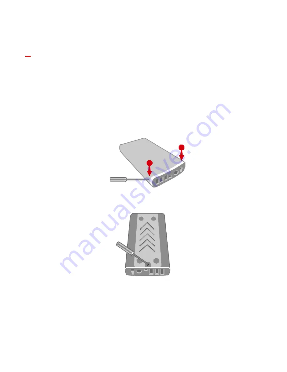
1)


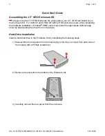
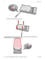
Disassemble the rear panel from the housing by removing one screw from each side of 

the housing with a Phillips screwdriver. 


2)


Remove the screw from the bottom of the Enclosure Kit.   


3)


Carefully remove the rear panel from the enclosure. 


2

1

Page 1 of 8

2

1/23/2005

file://E:\ONNTO-FOLDER\SC-M12CI+SC-M12O\35install.htm

Summary of Contents for SC-M12CI

Page 1: ...appropriate USB storage driver by downloading the driver from our website Hard Drive Installation Install a hard disk drive in the Enclosure Kit by completing the following steps 1 Disassemble the rea...

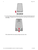
Page 2: ...d push the bottom panel out of the housing Adequate pressure must be applied when pushing the bottom panel out of the housing When disassembled the enclosure will appear as shown above Page 2 of 8 2 1...

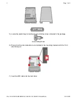
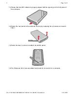
Page 3: ...luded in the package Auto limiting Screw 6 Ensure that the shock absorbers are installed in the mounting brackets with the thin side facing out 7 Insert the IDE cable into the hard drive Page 3 of 8 2...

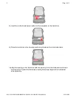
Page 4: ...ng positioning it between the shock absorbers 10 Align the opening on the hard drive with the opening in the shock absorber and insert the first screw Tighten the first screw ensuring that proper alig...

Page 5: ...e screws Align the edges of the hard drive platform with the integral rails and carefully slide the assembled platform into the enclosure housing 1 2 4 3 Page 5 of 8 2 1 23 2005 file E ONNTO FOLDER SC...

Page 6: ...12 Fasten the rear panel to the enclosure housing by replacing the 2 screws removed in step 1 13 Fasten the last 1 screw to reattach the bottom panel 14 The Enclosure Kit is now assembled and ready fo...

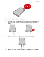
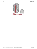
Page 7: ...e green LED indicator is active The orange LED indicator will blink during data transfer 2 Insert the USB or IEEE 1394 b connector into the corresponding port 3 Insert the USB or IEEE 1394 b connector...

Page 8: ...1 1 2 2 Page 8 of 8 2 1 23 2005 file E ONNTO FOLDER SC M12CI SC M12O 35install htm...

Reviews: