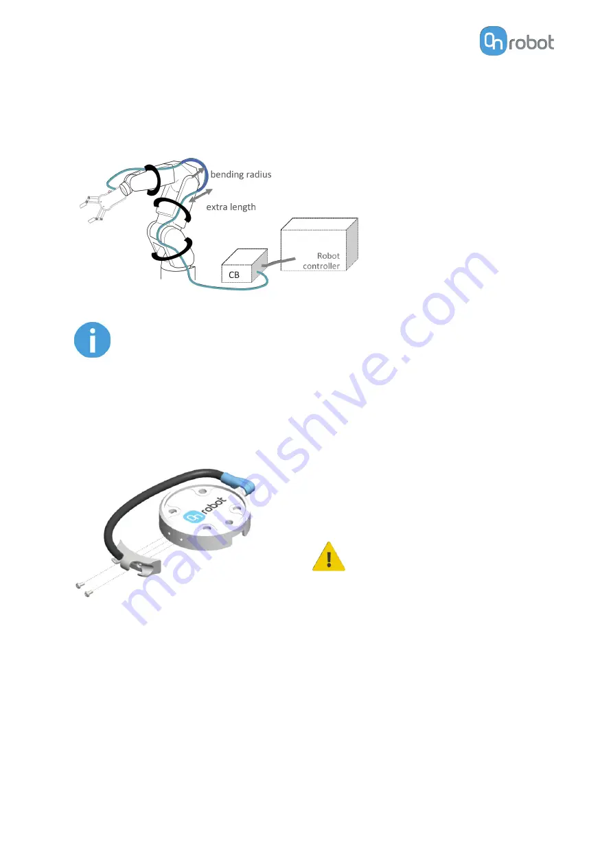
Connect the following cables to wire the system:
•
Tool data cable between the tool(s) and the Compute Box
•
Ethernet cable between the robot controller and the Compute Box
•
Power supply of the Compute Box
NOTE:
For the Quick Changer - Robot Side no cable is needed to be connected.
4.5.1. Tool Data Cable
4.5.1.1. Cable to 2FGP20
First connect the data cable to the tool.
Use the M8-8pin connector on the Quick
Changer or on the Dual Quick Changer.
Use the cable holder as illustrated on the left.
CAUTION:
Make sure to use the supplied
cable holder to prevent any
excessive strain on the 90-
degree M8 connector caused
by the rotation of the cable.
4.5.1.2. Cable to Compute Box
Then route the Tool data cable to the Compute Box (CB) and use the supplied Velcro tape
(black) to fix it.
HW INSTALLATION
17
Summary of Contents for 2FGP20
Page 1: ...USER MANUAL FOR UR ROBOTS v1 13 0 Original Instructions...
Page 62: ...Illustration Pad position Maximum force N 2 200 3 100 4 400 HARDWARE SPECIFICATION 62...
Page 71: ...8 2 3 Tools 8 2 3 1 2FGP20 All dimensions are in mm and inches HARDWARE SPECIFICATION 71...
Page 79: ...12 Certifications CERTIFICATIONS 79...
Page 80: ...12 1 EMC 12 2 2FGP20 Environment CERTIFICATIONS 80...
Page 81: ...12 3 Declaration of Incorporation 12 3 1 2FGP20 CERTIFICATIONS 81...


