background image

8. Hardware Specification

8.1. Technical Sheets

8.1.1. 2FGP20

Finger Grip Properties

Minimum Typical

Maximum

Unit

Payload

-
-

-
-

20
44.1

[kg]
[lb]

Total stroke

-
-

260
10.24

[mm]
[inch]

Grip width range *

170
6.69

-

430
16.93

[mm]
[inch]

Gripping repeatability

-
-

+/- 0.5
+/- 0.0197

-
-

[mm]
[inch]

Gripping force **

80

-

400

[N]

Gripping force tolerance

-

-

+/- 30

[N]

Gripping speed ***

16

-

180

[mm/s]

Gripping time (including brake activation)

-

600

-

[ms]

Hold workpiece if power loss?

Yes

Motor

Integrated, electric BLDC

* When pads are mounted, the minimum value is 158 mm and the maximum value is 418 mm.

** See 

Force vs Current Graph

*** At 6 mm stroke and 150 N. The typical value is 900 ms at 20 mm and 200 N.

Vacuum grip properties

Minimum Typical Maximum Unit

Vacuum

5
- 0.05
1.5

-
-
-

60
- 0.607
17.95

[%Vacuum]
[Bar]
[inHg]

Air flow

0

12

[L/min]

Payload (with delivered attachments)

-
-

2.5
5.51

[kg]
[lb]

Vacuum cups

1

4

[pcs]

Gripping time (measured with vacuum target 40 %)

0.25

[s]

Release time

0.4

[s]

Vacuum pump

Integrated, electric BLDC

Dust filters

Integrated 50 µm, field replaceable

HARDWARE SPECIFICATION

58

Summary of Contents for 2FGP20

Page 1: ...USER MANUAL FOR UR ROBOTS v1 13 0 Original Instructions...

Page 2: ...ode s 11 3 1 Operation via Compute Box 11 3 2 Operation via UR s Tool Connector 11 4 HW Installation 12 4 1 Overview 12 4 2 Robot Mount 12 4 2 1 Quick Changer Mounting 12 4 2 1 1 Quick Changer Robot S...

Page 3: ...37 6 5 Feedback Variables 41 6 5 1 2FGP20 41 7 Additional Software Options 42 7 1 Compute Box Eye Box 42 7 1 1 Ethernet Interface Setup 42 7 1 2 Web Client 44 7 1 3 Web Client Devices Menu 45 7 1 3 1...

Page 4: ...Robot Has Not Obtained an IP Address 76 10 2 Error During Operation 76 10 3 Changing the DIP Switch Does Not Take Effect 76 10 4 URCap Operation 76 10 5 Tool Functions Are Not Available 77 11 Warranti...

Page 5: ...l covers the following OnRobot products and their components 1 2 1 2FGP20 Tool Version 2FGP20 v1 1 2 2 Software and Firmware 1 2 2 1 URCap Software The manual covers the following software versions So...

Page 6: ...shall not be reproduced in whole or in part without prior written approval of OnRobot A S The information herein is subject to change without notice and should not be construed as a commitment by OnRo...

Page 7: ...to be used on collaborative robots and light industrial robots with different payloads depending on the end of arm tooling specifications OnRobot tools are normally use in pick and place palletizing m...

Page 8: ...obot A S that the robot application will not cause injury or damage even if robot application complies with all safety instructions OnRobot A S disclaims any and all liability if any of OnRobot tools...

Page 9: ...y role The integrator must consider the angle of contact with a human body e g orientate OnRobot tools and workpieces so that the contact surface in the direction of movement is as large as possible I...

Page 10: ...fety When setting the target force be aware that the maximum permissible force on quasi static contacts for collaborative applications is 140 N For further details please check the IS0 TS 15066 standa...

Page 11: ...t s could be used on both UR series via UR s Tool Connector which works with the following products 2FG7 or 2FGP20 or 3FG15 Only on e Series or MG10 1 or RG2 2 or RG6 2 or SG or VG10 or VGC10 Differen...

Page 12: ...s if applicable 4 2 1 Quick Changer Mounting 4 2 1 1 Quick Changer Robot Side Quick Changer Robot Side 1 M6x8mm ISO14580 8 8 2 Quick Changer ISO 9409 1 50 4 M6 3 Dowel pin 6x10 ISO2338 h8 4 Adapter R...

Page 13: ...2 Technical Sheets section 4 2 2 Tools 4 2 2 1 Finger and Vacuum Cup System Mounting Finger Mounting Mount the fingers by tightening the six M6x12 screws per finger with 3 Nm torque Vacuum Cup System...

Page 14: ...nical Sheet 4 2 2 2 2FGP20 Step 1 Move the tool close to the Quick Changer as illustrated The hook mechanism rod and hook tongue will keep the lower part locked once mounted Step 2 Flip the tool until...

Page 15: ...n the Clip on Bracket with the plastic srew 4 4 Wiring via Tool Connector DANGER Use only original OnRobot tool data cables The following devices are supported in the operation mode via tool connector...

Page 16: ...y powered off CAUTION Dual Quick Changer cannot be connected to the Tool Connector it must be used via Compute Box For CB3 Connect the Quick Changer for I O to the UR s tool connector DANGER Never con...

Page 17: ...le 4 5 1 1 Cable to 2FGP20 First connect the data cable to the tool Use the M8 8pin connector on the Quick Changer or on the Dual Quick Changer Use the cable holder as illustrated on the left CAUTION...

Page 18: ...ols 4 5 2 Ethernet Cable Connect one end of the supplied Ethernet UTP cable to the robot controller s Ethernet LAN port NOTE If the robot controller s Ethernet port is in use use a standard 4 port Eth...

Page 19: ...r supply to the Compute Box 24V connector NOTE To disconnect the power connector make sure to pull the connector housing where the arrows are shown and not the cable CAUTION Use only original OnRobot...

Page 20: ...e Series Select the Installation tab then select OnRobot Setup The following screen is shown Tap on the Installation tab in the top menu Then tap on the URCaps 5 1 1 1 Device Info In the normal view o...

Page 21: ...ds before you start your program To make sure that the device is connected check the Device info If the connected OnRobot product is changed always go to the Device info to check if the change was suc...

Page 22: ...lth and Firmware version are shown Update this will update the firmware if an update is available Depending on the selected devices different panels will become available to configure the devices RTDE...

Page 23: ...ters In this case the values will turn red in the OnRobot row Hide Variables A list of selectable variables When a variable is selected to hide it will not appear on the configuration panel TCP In the...

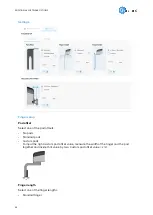
Page 24: ...alculated TCP 5 1 1 2 2FGP20 The configuration panels for the 2FGP20 are shown in the images below 2FGP20 In the normal view of the panel the selected Pad offset Finger length Finger height and Vacuum...

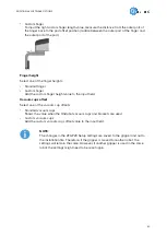
Page 25: ...ether and divide that value by two Custom pad offset value x 2 Finger length Select one of the finger lengths Standard finger Custom finger To input the right custom finger length value measure the di...

Page 26: ...field NOTE The changes in the 2FGP20 Setup settings are saved to the gripper and not to the installation file Therefore if the gripper is moved to another robot the settings will remain the same Howev...

Page 27: ...tten Dynamic TCP mode When unchecked the TCP is left unchanged Static TCP mode For further information and best practices on the TCP setting see 6 4 TCP Configuration section TCP offset Set the Linear...

Page 28: ...ion 6 1 1 2FGP20 6 1 1 1 2FGP20 Finger Grip When the 2FGP20 Finger Grip command is executed the gripper tries to reach the specified target parameters Width Force and Speed The different functions are...

Page 29: ...When the tool is connected to a CB3 robot via the tool connector the precision of the displayed Current width value is valid up to 1 mm resolution Will set the Target width Current width 5 mm when th...

Page 30: ...arget button recommended or by typing it manually Speed Sets the target release speed Executes the command Monitor Control Grip detected The gripper detects that a workpiece is gripped with the finger...

Page 31: ...the surface of the workpiece see 8 1 1 Technical Sheets section for more guidance on vacuum settings Executes the command Releases the vacuum NOTE Setting a lower vacuum gives a faster grip with less...

Page 32: ...robot will stop the movement and displays a popup window 6 1 1 4 2FGP20 Vacuum Release The 2FGP20 Vacuum Release command is used to release the grip of the workpiece by removing the vacuum Release ta...

Page 33: ...ess on the OnRobot icon Each OnRobot End of Arm Tooling has its own functionality and that is explained in the sections below To open up the toolbar in the CB3 press on the OnRobot icon on the top lef...

Page 34: ...To enable disable the toolbar press on the OnRobot logo on the top right corner and check uncheck the Enable toolbar checkbox OPERATION 34...

Page 35: ...6 2 1 2FGP20 To open up the toolbar follow the instructions under How to Access the Toolbar in the 6 2 URCap Toolbar section The toolbar for the 2FGP20 gripper is shown below OPERATION 35...

Page 36: ...Sets the target gripping force Buttons to open or close the gripper Vacuum Grip detected The gripper detects that a workpiece is gripped with the vacuum cups Current vacuum Displays the current vacuu...

Page 37: ...h with a specific speed width The width that the gripper will open or close to mm speed The speed that the gripper will try to reach fgp_vg_grip vacuum 20 Commands the 2FGP20 to turn on the vacuum to...

Page 38: ...ended to be used Dynamic TCP mode The mode could be selected on the TCP panel in the OnRobot Installation see in the 5 1 1 URCap Setup setup section In the following these two modes will be described...

Page 39: ...if only a single OnRobot device is used before the Waypoints are defined set the UR s Move command s TCP to use the OnRobot_Single If two OnRobot devices are used select OnRobot_Dual_1 or OnRobot_Dua...

Page 40: ...recommended to set the OnRobot_Default option as the Default TCP in the UR s TCP Configuration To let the system to automatically update the TCP during the program execution the UR s Move commands nee...

Page 41: ...Select Gripper 2 MoveJ Set TCP OnRobot_Dual_2 6 5 Feedback Variables 6 5 1 2FGP20 Feedback Variable Unit Description fgp_Busy True False Whether the 2FGP20 is busy or not fgp_Grip_Detected True False...

Page 42: ...nges will take effect DIP 3 sets the Compute Box Eye Box IP address ON Fixed IP 192 168 1 1 OFF Dynamic or Static IP can be configured via the Web Client DIP 4 sets whether the connected robot or lapt...

Page 43: ...ute Box Eye box IP Address of the Robot Computer Case 1 Static IP address The IP address 192 168 1 1 is already in use in your network or a different subnet needs to be configured The Compute Box Eye...

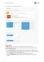
Page 44: ...ollowing steps Connect the Compute Box to your computer with the supplied UTP cable Power the Compute Box with the supplied power supply Wait one minute for the Compute Box LED to turn from blue to gr...

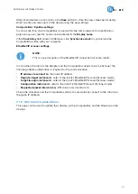
Page 45: ...ailable to all robots Update Update the Compute Box and the devices TCP CoG Calculate the TCP Tool Center Point and CoG Center of Gravity values for your OnRobot product combination The following menu...

Page 46: ...7 1 3 1 2FGP20 Monitor and control Actual Values and States This section displays information about the status of the gripper ADDITIONAL SOFTWARE OPTIONS 46...

Page 47: ...ent width value Current vacuum Shows the current vacuum level Device control Control the gripper as described below Fingers grip release To grip on a part set the Width the Force and the Speed sliders...

Page 48: ...tandard pads Custom pads To input the right custom pad offset value measure the width of the finger and the pad together and divide that value by two Custom pad offset value x 2 Finger length Select o...

Page 49: ...t field Vacuum cups offset Select one of the vacuum cup offsets Standard vacuum cups Shows the value when the OnRobot vacuum cups and brackets are used Custom vacuum cups Add the custom vacuum cups of...

Page 50: ...dress If it is set to Dynamic IP the Compute Box expects an IP address from a DHCP server If the network that the device is connected to has no DHCP server the Compute Box will not obtain an IP addres...

Page 51: ...s In case when the robot is the Adapter and the Compute Box needs to be the Scanner the following addition information is required for the communication IP address to connect to the robot IP address O...

Page 52: ...for the software and the firmware updates Software Update Click on Browse to search for the cbu software update file The Browse button will turn to Update Click on Update to start the software update...

Page 53: ...lator to calculate the TCP Tool Center Point and COG Center of Gravity values for your OnRobot product combination The TCP COG calculator will show the automatically detected settings NOTE Make sure t...

Page 54: ...of measure for the values you want to enter from the Size measurement Angle measurement Weight measurement and Angle type dropdown menus The calculator calculates the values which you can see in the T...

Page 55: ...On the Users tab click on the Add new user button to add more users ADDITIONAL SOFTWARE OPTIONS 55...

Page 56: ...There are three user levels Administrator Operator User Fill in the user information and click Save Later on to change any user information just click on the edit icon ADDITIONAL SOFTWARE OPTIONS 56...

Page 57: ...To prevent a user to sign in either could be deactivated by changing its Active status in the edit mode or removed by clicking the delete icon ADDITIONAL SOFTWARE OPTIONS 57...

Page 58: ...ower loss Yes Motor Integrated electric BLDC When pads are mounted the minimum value is 158 mm and the maximum value is 418 mm See Force vs Current Graph At 6 mm stroke and 150 N The typical value is...

Page 59: ...7 8 16 kg lb Weight With fingers pads on one finger bracket for cups and cups 5 2 11 46 kg lb Operating Conditions Minimum Typical Maximum Unit Power supply 20 24 25 V Current consumption 2000 mA Oper...

Page 60: ...ent If the workpiece is picked sideways make sure to orient the gripper with the moving finger on top as shown in the image below Also ensure that the bottom finger makes contact with the workpiece be...

Page 61: ...are made of aluminum with a cover of silicone The maximum force equally distributed in the blue area of the images below that can be applied to the finger pads is shown in the table below Illustratio...

Page 62: ...Illustration Pad position Maximum force N 2 200 3 100 4 400 HARDWARE SPECIFICATION 62...

Page 63: ...plied at the bottom of the workpiece To achieve this custom longer fingers are used and the fingerpads are attached horizontally This is the best way to get a firm grip By increasing the finger height...

Page 64: ...By doing so the applied force can be increased and a firmer grip is achieved Place the pads as close to the bottom of the workpiece as possible so the workpiece structure is stronger and can resist m...

Page 65: ...The vacuum solution has been designed to handle slip sheets and similar items The two most common configurations with the delivered bracket and cups are shown below Square Shape Row Shape Better for c...

Page 66: ...ase cut two of the tubes to 83 mm length NOTE It is important to always use the four air sources together Custom Vacuum Bracket If a custom bracket is required it can be made to fit the gripper accord...

Page 67: ...er 4 5A Dual Quick Changer Item 101788 104293 109878 Version Dual QC v2 Dual QC v2 4 5 Dual QC v3 Illustration If not specified the data represent the combination of the different Quick Changer types...

Page 68: ...DQC V3 and the QC R V2 QC R V2 4 5A DQC V2 DQC V2 4 5A can handle in a static situation The values for a situation with an acceleration of 2g are half of the static values 8 1 3 Compute Box 8 1 3 1 W...

Page 69: ...8 Minimum Typical Maximum Unit Output current altogether 100 mA Output resistance active state 24 Input DI1 DI8 as PNP Minimum Typical Maximum Unit Voltage level TRUE 18 24 30 V Voltage level FALSE 0...

Page 70: ...Quick Changer Robot Side Distance from Robot flange interface to OnRobot tool All dimensions are in mm and inches NOTE The cable holder on the left side is only required with the long 5 meter cable HA...

Page 71: ...8 2 3 Tools 8 2 3 1 2FGP20 All dimensions are in mm and inches HARDWARE SPECIFICATION 71...

Page 72: ...ulator to calculate the TCP and COG values for your OnRobot product combination The TCP COG calculator can be downloaded from www onrobot com downloads Using Compute Box Eye Box For more information s...

Page 73: ...Gravity mm Weight X 168 Y 0 Z 341 cX 1 6 cY 6 cZ 110 5 2 kg 11 46 lb TCP at the end of the fixed finger marked with the blue dot on the image below Suction cups and two pads on the moving finger as sh...

Page 74: ...on the nature of the workpiece and the working environment The gripper automatically de dusts the filters every time a grip is released However particles can eventually get stuck and build up inside t...

Page 75: ...70 alcohol Peroxide NOTE Long time exposure and high temperatures can have a negative effect on the materials especially on the sealings Use a dry cloth to wipe the product dry of the cleaning aids u...

Page 76: ...If an error occurs during operation try the following 1 Restart the robot and check the functionality 2 If the error is still present contact the distributor from where the product has been purchased...

Page 77: ...0 5 Tool Functions Are Not Available If the tool functions are not available grayed out in the program return to the Installation tab URCaps Device info and then back to the program TROUBLESHOOTING 77...

Page 78: ...warranty must be submitted within two months of the warranty default becoming evident Ownership of devices or components replaced by and returned to OnRobot A S shall vest in OnRobot A S Any other cl...

Page 79: ...12 Certifications CERTIFICATIONS 79...

Page 80: ...12 1 EMC 12 2 2FGP20 Environment CERTIFICATIONS 80...

Page 81: ...12 3 Declaration of Incorporation 12 3 1 2FGP20 CERTIFICATIONS 81...

Reviews: